- Set your project to tutorial_files.
- Open Cylinder Clamp
 Cylinder Clamp.iam.
 - Using the View Cube, Orbit, or View Face, adjust your view of the assembly so that it appears as follows:

The guard that you are going to create must fit over the base. By creating the sketch for a Contour Flange feature on the face of Cylinder Base.ipt, you can use the geometry of that part while defining your sketch profile geometry.
- On the ribbon, click
Assemble tab
 Component panel
 Create
, or right-click and select Create Component from the marking menu.
 - Enter my_2mm_guard in the New Component Name field in the Create In-Place Component dialog box.
- Click the Browse Templates button to the right of the Template field, which contains Standard.ipt as the default selection, and select the Metric tab in the displayed Open Template dialog box.
- Select the Sheet Metal (mm).ipt template, and click OK to enter the selection in the Create In-Place Component dialog box (replacing the default) and close the Open Template dialog box.
- Click OK to close the Create In-Place Component dialog box.
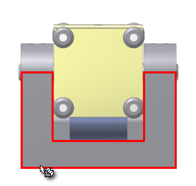
- In the graphics window, click to select the back face of Cylinder Base.ipt as shown:

Following the selection of the face shown, an empty sketch within the newly created sheet metal file displays. Next you create a simple open profile sketch to use to create a Contour Flange as the base feature of your guard.