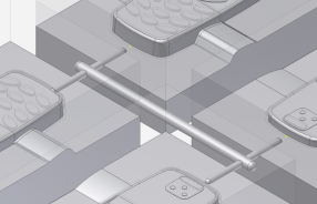
In this topic, you create the runner sketch by using a predefined runner balance and pattern type.
After the runner sketch has been created, you will add the runner to the mold assembly.
- On the ribbon, click Mold Layout tab > Runners and Channels panel > Auto Runner Sketch
 .
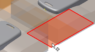
. - Select the surface that is highlighted in the following image. This surface was generated as a runoff surface.
- From the Balance menu, select H Balance.
- From the Pattern menu, select Pattern 1.
- In the Parameters section, enter the following:
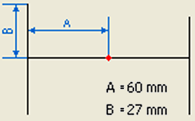
- A = 60 mm
- B = 27 mm
The A and B values define the runner as shown in the following image.
- In the Option section of the dialog box, clear the Activate Sketch Edit option. In this exercise, you are not required to edit the sketch.
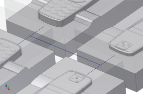
- In the Auto Runner Sketch dialog box, click OK. The runner sketch appears as shown in the following image.
- Click Runner
 .
. - From the Section Type menu, select Circle.
- For the size of the circular runner, enter the following:
- Diameter = 6 mm
- Select the two lengths of the runner sketch that make up the 120 mm run near the ends that are closest to the two subrunners. Selecting in these locations ensures that the cold slugs are located in the correct positions. Note: If the cold slugs do not appear in the correct locations or fail, change the start and end position options. Click in the Cold Slug Position cell and reversing the start and end options.
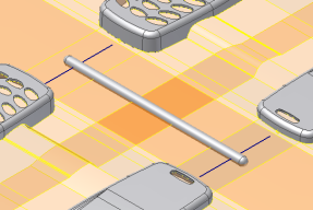
- Click Apply.
The runner appears in the model, as shown in the previous image.
Now that the main runner has been defined, you can define subrunners. The subrunners have a smaller diameter. For the size of the circular runner, enter the following:
- Diameter = 4 mm
- On one of the four subrunner sketch lines, select on the line at the end closest to the moldable part. Select points on the three remaining subrunner sketch lines in similar locations. It is important that you select near the moldable part so that the start and end locations for the cold slug position are defined properly.
- Click in the Cold Slug Length cells of the Create Runner dialog box and enter the following:
- Segment 1 = 0 mm
- Segment 2 = 0 mm
- Segment 3 = 0 mm
- Segment 4 = 0 mm
- Click OK to complete the runner. The model appears as shown in the following image.
