In this topic, you define the gate locations for the Exp-Mobile Top and Exp-Mobile Bottom components.
- On the ribbon, click Mold Layout tab > Runners and Channels panel > Gate Location
 .
. - Select the model shown in the following image to satisfy the Plastic Part selection in the Gate Location dialog box.
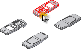
- The two instances of the Exp-Mobile Top model are available for specifying the Gate Location.Rotate the model to match the following image. We create a gate location in each of the areas noted.
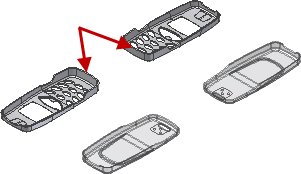
- Zoom in to display the end of the Exp-Mobile Top model shown in the following image. Select a point near the center of the thin planar surface to satisfy the Location selection.
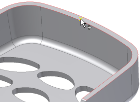
Selecting on this surface constrains the gate location to this surface. The gate location on the surface is initially defined as the point that you selected. Exact U and V values can be assigned in the Gate Location dialog box to change this position.
- In the Value field of the Gate Location dialog box, enter the following:
- Position U = 0.5
- Position V = 0.09
- Make sure Copy to all pockets is checked. This copies the gate location to all patterned elements. Click Apply to create the gate location on both instances.
- Click OK on the File Naming dialog box to accept the defaults.
- Click the Plastic Part Part selector.
- Select the component Exp-Mobile Bottom as shown in the following image.
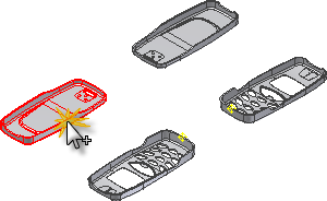
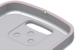
- Zoom to the area of the Exp-Mobile Bottom model shown in the following image. Select a point near the middle of the lower surface to satisfy the Location.
- In the Value field of the Gate Location dialog, enter the following:
- Position U = 0.5
- Position V = 0.04
- Make sure Copy to all pockets is checked. This copies the gate location to all patterned elements. Click Apply to create the gate location on both instances.
- Click Done to finish the command.
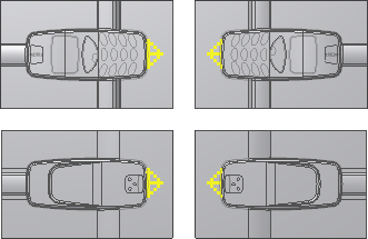
- The points appear in the mold assembly on all models and the Gate Location is present in the browser under each parent part.
Note: The Gate Location dialog box provides a Suggest tab that runs a simulation on the moldable part. It also provides locations for a user-specified number of gates. The About this tutorial tutorial explains how to run a Gate Location simulation.