Add a contact set to an assembly and then set limits on the motion. Use a contact set to stop movement when bodies collide, as they would in the physical world. To avoid slow calculation time, limit the number of components in a contact set to only the components necessary.
- Open the file Cylinder Body Sub_Assy.iam, located in \Tutorial Files\Cylinder Clamp.
- Use the left mouse button to click and drag the blue shaft on the assembly. The shaft can move in a linear and rotational direction. You can also pull the piston and shaft completely out of the body. The linear and rotational freedom is intentional so that the piston can move in a higher-level assembly.
Before proceeding, use Undo to restore the piston to the position it was in when you opened the file.
-
 On the ribbon, click
Inspect tab
On the ribbon, click
Inspect tab
 Interference panel
Activate Contact Solver
. The command activates, but no components belong to the contact set yet.
Interference panel
Activate Contact Solver
. The command activates, but no components belong to the contact set yet. - In the browser, right-click each of the following components, or in the graphics area right-click the components. Enable Contact Set in the context menu.
- Cylinder Head Cover_Front
- Cylinder Head Cover_Back
- Piston
- Push and pull on the piston shaft. The piston body movement is limited by the physical contact with the front and back cylinder heads. Note: Rapid mouse movement allows the piston to pass through the cylinder cover bodies. This intentional behavior enables you to move contact set members in or out of a closed body.
- Pull the piston to the end of its stroke. In the Interference panel, click Activate Contact Solver again to deactivate it.
- Right-click the Cylinder Body and clear Enabled to make it easier to select internal parts.
When you turn off Enabled, a component displays transparently for reference, and you cannot select it. A component that is not enabled appears green in the browser. To re-enable a component, right-click the component in the browser, and click Enabled.
- Start the Joint command. If the dialog box does not display, press the three dots (...) in the mini toolbar to open. Do not change any settings.
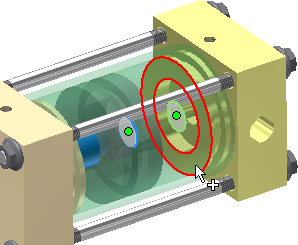
- Click the end face of the Cylinder Head Cover- Back, as shown in the following image.
- Rotate the assembly or use Select Other to select the back face of the Piston, as shown in the previous image.
If the joint type defaults to Rotational or other joint type, click the drop down and change the type to Cylindrical.
- Click More, and specify the following limits for the linear position:
Check Start and specify a value of 0mm
Check Endand specify a value of 35mm
- Click OK to create the joint and close the dialog box.
Drag the piston rod. The piston stops at either end.
- In the browser, right-click the cylinder body and select Enabled.
Experiment with Limits settings to change the range of motion. In the browser, edit the joint. Expand the Piston, right-click the Cylindrical joint, and select Edit.