Constrain the piston to the Base and the 2D sketch part. The next portion of the exercise assumes Cylinder_Main.iam and Cylinder Body Sub_Assy.iam are both open.
- On the ribbon, click
View tab
 Windows panel
Tile
.
Windows panel
Tile
. - Click inside the window containing Cylinder Body Sub_Assy.
-
 Click and drag the assembly icon from the browser to the Cylinder_Main window. The subassembly is inserted in the main assembly without using the Place Component command.
 - Save and Close the subassembly file.
- Maximize the window containing the main assembly.
- Start the Constrain command.
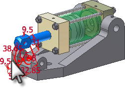
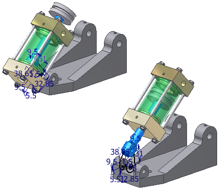
- Apply a Mate axis/axis constraint between the 2D sketch and the hole in the piston rod, as shown in the following image.
When the subassembly is open in a separate window, the piston is free to move. When you insert the subassembly in the upper level assembly, the free movement is disabled. To finish constraining the subassembly in the main assembly, you must enable the freedom to move in the upper-level assembly. If the piston is not free to spin, the subassembly cannot rotate into the correct position.
- Locate Cylinder Body Sub_Assy in the browser.
- Right-click the subassembly, and select Flexible in the context menu. It activates the freedom of movement that was present in the subassembly in the upper level assembly.
The subassembly icon in the browser changes to indicate that Flexible status is active.
On the ribbon, click Assemble tab Position panel
Rotate
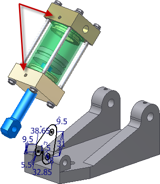
to move the subassembly until the tapped holes in cylinder end caps are facing up, as shown in the following image. Right-click, and select Done.
Position panel
Rotate
to move the subassembly until the tapped holes in cylinder end caps are facing up, as shown in the following image. Right-click, and select Done.Unlike a view rotation, this command physically rotates a component in space. If you take the time to orient components relative to each other before you apply constraints, the constraints behave more predictably when applied.
- Start the Constrain command. Accept the default settings.
- In the browser, expand Cylinder Base and Cylinder Body Sub_Assy to expose the browser tree. Expand the Origin folder in Cylinder Body Sub_Assy.
- Select Work Plane1 under Cylinder Base and YZ Plane in the Origin folder under Cylinder Body Sub_Assy to apply a Mate plane/plane constraint.
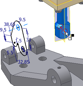
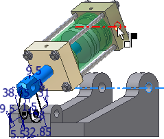
If the subassembly turns inside-out, drag it toward the back of the base to correct the orientation as shown in the following image. The constraints you applied limit the movement.
- Start the Constrain command. Accept the default options.
- Select the center of each of the holes indicated in the following image to place a Mate axis/axis constraint.
- Drag the 2D sketch part to check the motion of your digital prototype.