In a top down workflow, create a part or subassembly in the assembly using Create Component. At the prompt to select the sketch plane, select an origin plane, a work plane, or part face. This pick establishes the coordinate system for the new component. In the Create In-Place Component dialog box, the option Constrain sketch plane to the selected face or plane is not enabled by default. This option applies a Flush constraint between the new component and the selected face or plane. Clear the check mark to apply no initial constraint.
The following are some of the advantages to creating a part in the assembly:
- Use a top-down workflow to design a component in place.
- Project edges from other components to a part sketch.
- Measure clearance space for the component envelope.
To create a part in the assembly, start the Create Component command, follow the steps described previously, and use the provided clamp sketch as a guide.
To save time, insert a 2D part in the assembly. Apply assembly constraints to position the 2D sketch on the base. Then extrude the sketch into a solid.
- Start Place Component.
- Select Clamp Sketch.ipt and then click Open.
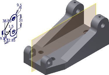
- Right-click before placing and select Rotate Y 90°. Right-click again and select Rotate X 90°.
The sketch component is oriented as shown in the following image.
- Click in the graphics window to place one copy and then right-click and select OK, or press ESC to exit the command.
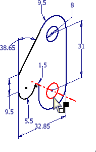
- Start the Constrain command and move the cursor over the edge of the sketch circle.
When the axis displays, select the circle, as shown in the following image.
- To select an axis as the second half of the constraint, move the cursor over the inside of the hole on the base. When the axis preview displays, select inside the hole, as shown in the following image. Do not select the edge of the hole when a green dot appears. The dot is a point constraint, and does not result in an axis to axis constraint.
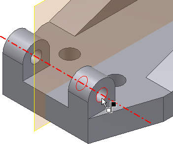
- Click OK to create the constraint.
Hold the left mouse button down as you select the 2D sketch, and then push or pull on the geometry. The movement is limited to the axis you defined.
- In the browser, under Clamp Sketch, expand the Origin folder, right-click the XY Plane, and turn on Visibility
- Start the Constrain command and leave the default set to Mate.
- On the clamp sketch, select the XY Plane to satisfy the first pick.
- Select the work plane in the center of the base, as shown in the following image.
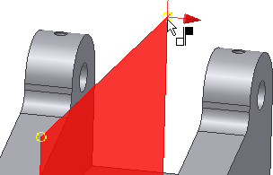
The mate constraint displays in the preview.
 On the lower right corner of the dialog box, click the Flush option. Click the OK button to apply the constraint and finish the command.
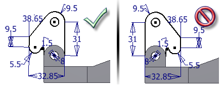
 The following image shows the correct Mate/Flush solution on the left. The solution on the right is the result of a Mate/Mate. If you made a mistake, you can edit the constraint and apply the correct solution. In this case, the correct selection was specified for you. In the future, use the preview to help you decide whether to apply a Mate/Mate or a Mate/Flush constraint between two planes.
- Click the Clamp Sketch, and hold the left mouse button down. Drag the 2D sketch. The part still has one degree of rotational freedom. All ungrounded components initially have six degrees of freedom: three translational (linear X, Y, and Z), and three rotational (rotational X,Y, and Z).
- Click
View tab
 Visibility panel
Degrees of Freedom
. A rotational arrow on the Clamp Sketch indicates the part still has rotational freedom. Select the Degrees of Freedom command again to turn it off.
Visibility panel
Degrees of Freedom
. A rotational arrow on the Clamp Sketch indicates the part still has rotational freedom. Select the Degrees of Freedom command again to turn it off. - Save the file as Cylinder_Main.iam.