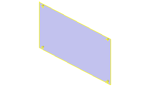
In this section, you add a planar surface to the plastic part model. It is used as a reference for the model changes required to eliminate the undercut.
- Drag the End of Part marker from the bottom of the Model browser list to just after the Work Point4 feature. The model appears as shown in the following image.

- Turn off the visibility of Solid1 in the Solid Bodies node.
- Turn on the visibility of Work Point1, Work Point2, Work Point3, and Work Point4.
- On the ribbon, click
3D Model tab
 Work Features panel
 Work Plane
 . On the browser, select Work Point1, Work Point2, and Work Point3 to create a plane. The model appears as shown in the following image.
- On the ribbon, click
3D Model tab
 Sketch panel
 Create 2D Sketch
 and select the edge of the plane you created as the sketch plane reference.
 - On the ribbon, click
Sketch tab
 Draw panel
 Project Geometry
 and select Work Point1, Work Point2, Work Point3, and Work Point4.
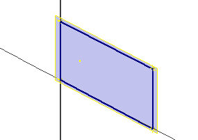
 - Sketch four lines connecting the projected points, as shown in the following image.

- Finish the sketch.
- On the ribbon, click
3D Model tab
 Surface panel
 Patch
Patch
 and select the closed boundary loop created by the sketch. Click OK.
 - Turn off the visibility of Work Point1, Work Point2, Work Point3, Work Point4, and the Work Plane. The new surface is the only feature displayed. The surface was added to the model to use as a reference for new work points. The new work points properly locate the bosses in the modified model.