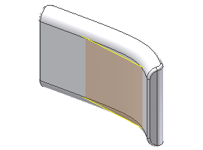
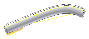
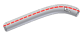
In this section, you use the Move Bodies command to rotate the solid body and surfaces by 10 degrees. It adjusts the parting surface for the model and avoids the undercuts.
- Drag the End of Part marker after the Shell1 feature.
- Return to the Solid Bodies node and turn on the visibility of Solid1, as shown in the following image.

- Reorient the model to a Front view. Turn on the visibility of the Parting Surface and BatterySplitSurface. The model appears as shown in the following image.

- On the ribbon, click
3D Model tab
 Modify panel
 Move Bodies
 .
. - Select Solid1 from the Solid Bodies browser node or in the graphics window as shown in the following image.

- Click Free Drag
 in the Move Bodies dialog box to activate the drop-down arrow. Scroll the list and select Rotate about line
  in the drop-down list. Select the Z axis in the Origin node as the rotation axis. Enter 10 deg in the Angle box.
 - Pick the Bodies select arrow again and pick Srf1, Srf2, and Srf5 in the Surface Bodies folder.
- Click OK. The model appears as shown in the following image.

- Turn off the visibility of the Parting Surface, BatterySplitSurface, and Solid1.
- Reorient the model to the Home view.
- On the ribbon, click
3D Model tab
 Work Features panel
 Point
Point
 and select one of the four corners of the boundary patch to create a work point. Repeat the command until there are work points at all four corners of the boundary patch. These points are required because the Move Bodies command cannot rotate points. The original reference points were used to locate the bosses in the solid body. Because the points were not rotated, the bosses are incorrectly positioned. Using these new points the bosses can be redefined for proper placement.
 - Turn off the visibility of the Boundary Patch.
- Turn on the visibility of Solid1 and PartingSurface.
- On the ribbon, click
3D Model tab
 Modify panel
 Move Bodies
 .
. - Select Srf1 from the Surface Bodies node or directly from the model to satisfy the Bodies selection, as shown in the following image.

- Maintain the Free Drag option for moving the bodies and enter 0 mm as the X offset and -0.25 mm as the Y Offset. Notice the small change in the position of Solid1 relative to the PartingSurface. This surface was moved down to correct the parting line for the model.
- Click OK.
- Turn off the visibility of PartingSurface.