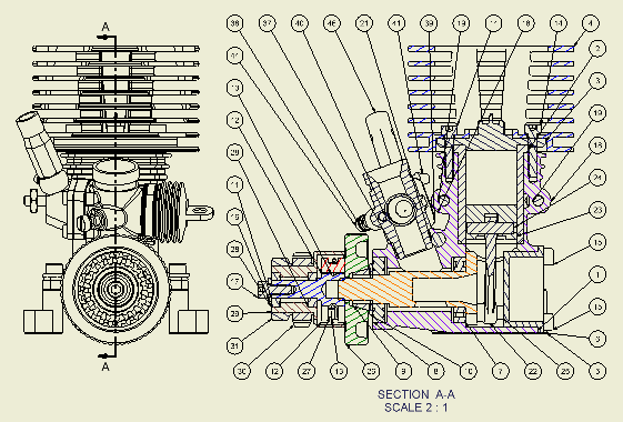
Creates a full, half, offset, or aligned section view from a specified parent view. You can also use Section view to create a view cutting line for an auxiliary or partial view. A section view is aligned to its parent view.

In the following image, a section view was used to expose components for ballooning.

|
Access: |
Ribbon:
Place Views tab
 Create panel
 Section
|
View/Scale Label
|
Specifies the view label and scale. |
|
|
View Identifier |
Edits the view identifier string. |
|
Scale |
Sets the scale of the view, relative to the part or assembly. Enter the scale in the box, or click the arrow to select from a list of commonly used scales. You can enter a scale that is not on the list. The new scale appears above a line in the list and is available until you close Autodesk Inventor. It is not added to the scale list from the Standard style. |
|
|
Displays or hides the view label. |
|
|
Edits the view label text in the Format Text dialog box. |
Style
|
Sets the display style for the view. The default display style for a section view is Hidden Line Removed. To change the display style, click a command. |
|
 |
Sets the display to show hidden lines. |
 |
Sets the display to remove hidden lines. |
 |
Sets the display to a shaded rendering. |
Section Depth
|
Depth Control |
Controls the section depth. Select Full to create the section view to all geometry beyond the cutting line. Select Distance to specify a distance of viewing in model units beginning from the cutting line. |
|
Distance |
Sets the distance of the section. Note: Set the section depth to zero to revert to the smallest available section depth. This is not a true zero-depth section. The actual value is 0.000012.
|
Slice
|
Include Slice |
When checked, the Section View is created with some components sliced and some components sectioned, depending on their Browser attributes. |
|
Slice All parts |
When checked, the Browser attributes are overridden and all components in the view is sliced according to the Section Line geometry. Components that are not crossed by the Section Line does not participate in the resulting view. The Section Depth fields are disabled when this option is checked. Note: This option is only available when Include Slice option is checked.
|
Method
|
Specifies the method of projecting the section view when you either sketch a multi-segment section line or select a view sketch containing a multi-segment section line. |
|
|
Projected |
Created projected view from the sketch line. Note: This option is set as default if all segments are exactly 90 degrees.
|
|
Aligned |
When checked, resulting section view is perpendicular to the line of projection. Body cut lines do not display in the resulting view. Aligned option is not available for a child (dependent) view. Note: This option is only available when Include Slice option is checked.
|