When you create a section view, you draw a line that defines where to cut the section view. A section view can also be created by specifying a line in a drawing sketch that is associated with the parent view.

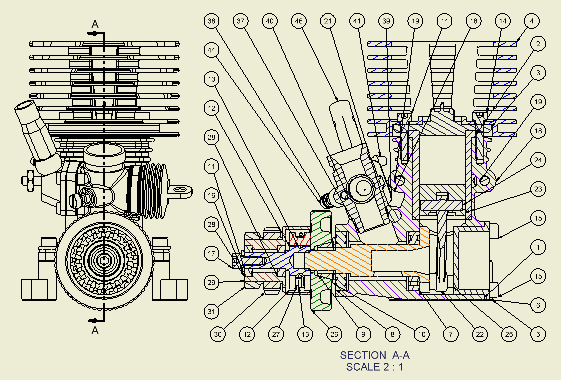
In the following image, a section view was used to expose components for ballooning.

A view cutting line knows what types of views can be projected from it. Depending on how the line is created, it can define the type of section view or define a boundary for a partial view.
The length of the cutting line defines the extent of the section view. A cutting line that passes only partially through the model view results in a partial section view.
If you draw the view cutting line outside the parent view, it defines a plane from which to project an auxiliary view.
- In an assembly view, components can be excluded from sectioning. In the browser, right-click the component to exclude, and then select None.
- When creating a child (dependent) view, the section attributes of the parent view are copied to the child view, but they are not associative. Section view attributes changed on the parent do not affect the child. You can modify the settings without affecting the parent view attributes.
- Section and visibility settings are copied to projected views. All views provide independent control of section and visibility settings. Changes to settings only affect the view where the changes of the contents settings are made.
- The section and visibility settings of a view affect the results of a breakout view operation.
- Section views based on presentations show trails. You can turn visibility of one or all trails on and off.
- If you used inferred or explicit constraints to place the view cutting line, you must edit the sketch to remove the constraints before you can drag the constrained points or line segments.
View cutting lines
As you draw a view cutting line, constraints to features and edges are inferred as you move the cursor. If you place a point while an inference line is displayed, the constraint is automatically applied.
After you complete the view cutting line, the available views preview as you move the cursor in the graphics window. After you place the view, it can be moved only within the limits of view cutting line constraints.
Specifying drawing sketch lines for view cutting lines
After you associate a drawing sketch with a view, you can use any line within the sketch that passes through the view geometry to specify the view section.
Section view alignment
A view defined by a view cutting line is usually aligned to the parent view. It can be moved within the alignment constraint. If you remove the alignment, the view can be moved freely in the drawing, and the view cutting line with its arrowheads and text label are displayed on the parent view.
Hatching in section views
Hatch patterns are automatically applied to section views when you create them. The active Hatch style defines the pattern, scale, shift, and other attributes of the hatch.
 |
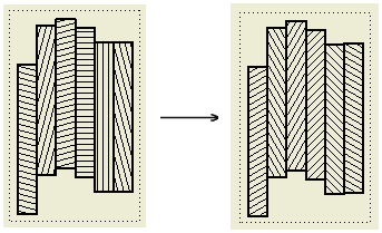
When multiple parts are cut in a section view, a specific hatch angle is applied to each section hatch. Default Section Hatch Angles are specified by Preset Values on the General tab of the Standard style pane. The final hatch rotation for cut views includes also the rotation angle defined in the Hatch style. If appropriate, use Style and Standard Editor to edit the default values of the hatch angle. Note: The default hatch rotation angles apply on creating section views. If the setting in the Standard changes, existing section views keep the hatch rotation angle as an object override.
|
To change the default hatch in cut views:
- Edit the current Hatch style or select another Hatch style for the Section Hatch object in Object Defaults.
- Change the default Section Hatch Angles on the General tab of the Standard style pane. Section Hatch Angles define hatch rotation for particular sectioned parts.
- Load hatch patterns from an external PAT file and set them in the Hatch style.
- Map materials to hatch patterns on the Material Hatch Pattern Defaults tab of the Standard style pane.
To edit properties of a hatch in a cut view, right-click the hatch and click Edit. Then change the hatch attributes in the Edit Hatch Pattern dialog box. All edits are kept as property overrides.
To change the Hatch style for a section hatch, select another style in the Style list box on the Annotate tab of the ribbon. The selected Hatch style is applied to the hatch object and all overrides are discarded.
By Material hatch pattern
You can map materials to hatch patterns. Open the Style and Standard Editor, click the active Standard style and open the Material Hatch Pattern Defaults tab. Then import materials or create a list of materials manually, and map hatch patterns to materials.
If material of a component is defined in the hatch pattern map, then the By Material hatch pattern is used whenever the component is cut. The By Material option is enabled for the component. Otherwise, the hatch pattern from the Hatch style assigned to the Section Hatch object in Object Defaults is used. The By Material option is disabled for the component.
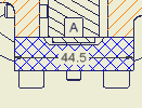
Cross hatch clipping
 |
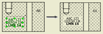
Select the Cross Hatch Clipping option on the Drawing tab of the Document Settings dialog box to break hatching around drawing annotations in cut views. |
Notes:
- To enable clipping around user-defined symbols, select the Symbol Clipping option for individual symbol instances.
- The cross hatch clipping is not supported for datum targets and in isometric views.
 |
Tip: Hatching is clipped on the bounding box of note text. If appropriate, change the size of the bounding box to resize the clipped area.
|
Styles for section view annotations
The default appearance of the section line, arrows, and label text style is specified in the View Annotation style. To change the default settings, click
Manage tab
 Styles and Standards panel
 Styles Editor
and edit an existing or create a new a view annotation style.
To change the default properties of the section view label, choose
Manage tab
 Styles and Standards panel
 Styles Editor
, select a Standard style and open the View Preferences tab on the Standard style panel.
Editing of section views
After you place a section view, you can change the definition of the view, or even the type of view, by dragging the elements of a view cutting line in the graphics window.
- Drag a point to shorten or lengthen a line segment.
- Drag a line segment to move it, and shorten or lengthen adjoining line segments.
- Drag an arrowhead to change its direction or the length of the landing.
- Drag a point to change the angle of a line segment.
As you change the view cutting line, the dependent view updates to reflect the new view definition.
Inheritance of the section and breakout cut
Isometric projected views created for section views inherit the section cut by default. Orthographic projected and auxiliary views support the inheritance of the section, but it is switched off by default.
Isometric projected views created for views with a breakout inherit the breakout cut by default. Orthographic projected and auxiliary views do not support inheritance of breakout operations.
Slice operations in section views
You can create a section view with some sliced components and some sectioned components depending on their browser attribute settings.
You can optionally choose to override browser component settings and slice all parts in the view according to the section line geometry. Components that are not crossed by the section line do not participate in the slice operation.