In this section, you manually create the gate location.
Gate locations are coordinates on the surface of the moldable part, which indicate where the physical gates will be placed. You can manually locate the gate position, or use the Gate Location analysis to recommend the best locations for the appropriate number of gates automatically.
Tip: To include a gate location in a pattern, check Copy to all pockets. Clear the check box to create a unique gate location.
Note: You can access the Gate Location command in both the Mold Layout tab, and the Core Cavity tab.
- On the ribbon, click Mold Layout tab > Runners and Channels panel > Gate Location
 . The core and cavity are removed from the display, and that the moldable part becomes visible to enable the specification of a gate location point. The Gate Location dialog box is also displayed.
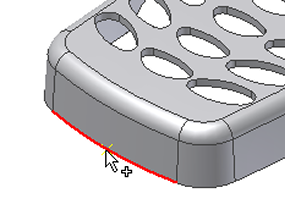
 - Zoom in on the end of the model. Select a point near the mid-point of the lower edge, as shown in the following image. Because you selected an edge and not a vertex, a value indicating the edge length ratio appears in the dialog box. Note: If you select a vertex, the exact coordinates of the point appear. If you select on a moldable part face, U and V parameter values appear and can be modified.

- In the Value field of the Gate Location dialog, enter the value 0.5 and then click Apply. Additional gate point locations can be defined if a part requires multiple gates. This tutorial uses a single gate.
The Gate Location dialog box provides a Suggest tab. An analysis runs on the moldable part and suggests locations for a user-specified number of gates. The About this tutorial tutorial explains how to run a Gate Location analysis.
- Click OK in the File Naming dialog box to accept the defaults and create the gate location.
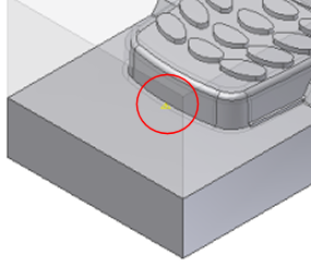
- Click Done on the Gate Location dialog box to finish the gate location process. Close the dialog box, and return to the display of the core and cavity. The point appears in the mold assembly, as shown in the following image.
