In this section, you manually create a runner sketch.
The runner sketch must be created before the features of the feeding system can be added. The feeding system, which consists of runners, gates, sprues, and cold wells, evenly distributes plastic melt from the machine nozzle to all the mold cavities.
The runner sketch can be sketched manually or added automatically. The Auto Runner Sketch command enables you to base the runner sketch on layouts that are commonly used in mold design. The About this tutorial tutorial further explains the Auto Runner Sketch command.
The Manual Sketch command enables you to enter the sketch environment and draw a runner sketch.
- On the ribbon, click Mold Layout tab > Runners and Channels panel > Manual Sketch
 . The Manual Sketch command is located in the Auto Runner Sketch menu.
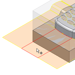
 - Select the planar runoff surface shown in the following image as the placement plane for the sketch.

- Make sure the Type is set to Runner Sketch, then click OK on the Manual Sketch dialog box to activate the sketch environment.
- On the keyboard, press F6 to orient the model in the Home View. In the upper-right corner of the graphics window, click Top on the ViewCube to orient the sketch.
- Zoom in on the end of the model where you created a gate location in the previous section.
- On the ribbon, click Sketch tab > Draw panel > Line
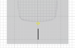
 . To represent the runner, sketch the line shown in the following image. The length of the line is not important, but the sketch of the line should not extend into the mold. Later in this tutorial, you create a gate to connect the runner to the mold.
- On the ribbon, click Sketch tab > Draw panel > Project Geometry
 . Select the previously created gate location point to project that gate point into the current sketch.
 - Click Sketch tab > Constrain panel > Coincident Constraint
 . Choose the projected point and the sketched line to ensure that they are aligned.
 - Click Sketch tab > Exit panel > Finish Sketch
 to complete the sketch and return to the Mold Design environment.
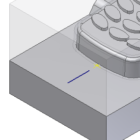
 - On the keyboard, press F6 to return to the Home View. The runner sketch and the gate point appear as shown in the following image.
