Create wires and cables in the harness assembly.
Before you begin creating harness objects, such as wires and cables, you can set several default configuration options for forward creation. The defaults are set on the Harness Settings dialog box.
- Activate Harness Assembly1, if not already active.
- Right-click Harness Assembly1, and select Harness Settings.
- On the General tab, examine the settings of interest and ensure the Use Surfaces for All Segments and Wires is selected (it is selected by default). Choose this setting for faster processing times while creating and editing. To represent segments and wires with solids, clear the check box.
- On the Wires/Cables tab, under Natural Curvature, select Without Natural Curvature
 to display the wires as straight lines for the harness assembly.
 - Click the other tabs and examine the various settings.
- Click OK.
Manually insert wires and cables.
- On the Cable and Harness tab, Create panel, click Create Wire.

- On the Create Wire dialog box, accept the default wire ID (Wire1). The Wire ID is Wire plus an incremental number (the numbers start at 1).
- From the list of wires, select the wire to insert:
- For category, select Generic.
- For name, select 22AWG-GRN.
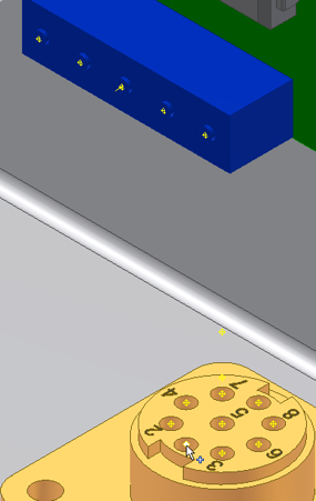
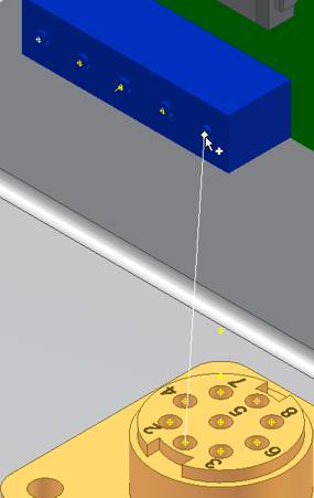
- To start the wire, select Pin 1. Move the cursor over the pins on part 360124. When the tooltip displays as U3 Pin 1, click the work point. If you have Dynamic Prompts turned on, the tooltip provides additional information.
 Note: To turn off Dynamic Prompts, on the Tools tab, click Application Options . On the General tab, clear the check box for Show command prompting (Dynamic Prompts).
 - To end the wire, select Pin 2. Move the cursor over the pins on part LTP. When the tooltip displays as J12 Pin 1, click the work point.

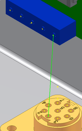
- To create the wire, click Apply. The wire is created as centerline or rendered, depending on your display setting. By default, the display is set to centerline for wires and cables.

- On the Create Wire dialog box, click Cancel to exit.
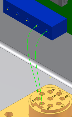
- Before you add the second wire, access the Harness Settings dialog box for Harness Assembly1. Change the natural curvature setting for wires and cables to With Natural Curvature.

- Add one more wire connecting U3 Pin 2 to J12 Pin 2. Note: If the wires are still depicted as straight lines, go back and reauthor the connectors. Natural curvature only displays between authored connectors, since the authoring process defines the Outward Direction.

- Click Finish Cable and Harness to exit the Cable and Harness environment. You can view the added wires in the browser when you expand the Wires folder under Harness Assembly1.