In the first section of this exercise, we will create two spline cross sections and one spline rail to use in a Loft operation.
- To begin, set your active project to tutorial_files. Navigate to the Splines folder and open the file spline_1_start.ipt. Orient to the Front view on the View Cube.
Notice that the part is wedge shaped and one end is wider than the other.

-
 Start a 2D sketch on the face indicated.
-
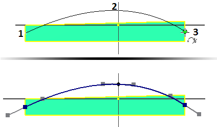
 Start the Spline command. Refer to the following image for placement. Place a fit point at the mid-point (green dot) of the vertical line on the left (1), another directly above the origin (2). Double-click to place the final point (3) at the mid-point of the vertical line on the right. This action creates the spline. You can also right-click and choose Create to finish the spline segment.
 - Right-click and select Done or press the Escape key to exit the command.
 Note: Fit points at the end of a spline are square. Fit points along the curve are diamond shaped so you can identify the start and end of joined spline segments.
When you create a spline, handles appear at each fit point in a passive state. Handles are shape manipulators. You can drag or dimension to a fit point without activating a handle. If the handles are not visible, select a spline in the sketch to display the active and passive handles.
- Activate the handle on all fit points. To activate a handle use one of the following methods:
- Press and drag anywhere on the handle.
- Right-click a fit point and choose Activate Handle in the context menu.
Tip: Handle manipulation changes the shape of a spline. It is sometimes necessary to "undo" a spline handle manipulation. Depending on how many handles were manipulated, a normal Undo command might not produce the required results. When a spline is selected, there are two context menu commands available for reversing handle manipulations:- Reset All Handles Reverses all handle edits and restores the spline to the natural solve state. Active handles remain active.
- Reset Handle Reverses a handle edit on a selected fit point or handle, or the handle nearest the cursor. The reset uses the current spline shape. If other handles were modified, the reset may not return the handle to the original solve state. The handle remains active
-
 Right-click the middle fit point and enable Curvature in the context menu.
 Tip: Enabling Curvature also activates the linear handle. Enabling the linear handle does not activate Curvature.
 -
 Place a horizontal constraint on all handles.
 -
 Place a vertical constraint between the middle fit point (not the handle) and the part origin.
 -
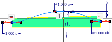
 Place a dimension on each handle with a value of 1. A linear handle dimension is unitless and indicates the distance the spline is tangent to the handle.
 - Place a radial dimension of 110-mm on the middle fit point curvature handle. A radial dimension is not a unitless dimension.
- Place a 9-mm vertical dimension from the projected Origin point to the middle fit point.
The following image shows the completed sketch.

-
 Finish the sketch. The 9-mm dimension persists; the handles and all handle dimensions are visible only when the spline is active.
 - Start the Save As command and save the file as Spline_Skills1.ipt.
To create an exact duplicate of the spline on the other side of the part perform the following steps.
-
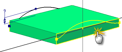
 Orient the part to match the view in the following image and start a new sketch on the indicated face.
 -
 Start the Project Geometry command and project the spline to the new sketch.
-
 Finish the sketch.