- Press E on the keyboard to invoke the Extrude command, or right-click and select Extrude from the marking menu.
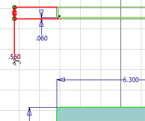
The "front" view of the inserted DWG file contains geometry which represents the outside of the cover and the thickness of the material that makes the cover sides. To create this part, you select both of the regions displayed in the front view inside of the 6.30" x 6.30" rectangle.
Notice that you must click inside both sketch loops. Click to play the animation which shows the selections needed.
- In the value input box in the in-canvas display, or the Extents field of the Extrude dialog box, highlight the 1 in value.

- Select the .560 dimension value (the full depth of the cover) in the "top" view of the inserted geometry.

- The program replaces the default extrude distance of 1 inch by the existing dimension, as represented by the parameter name d5.

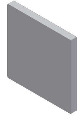
- Click the green Ok button to create the base feature that will become the electrical panel cover and exit the command.
- Press F6 to position the part in the Home view.
