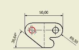
- On the ribbon, click
Annotate tab
 Feature Notes panel
 Hole and Thread
 .
. - Move your cursor near the 10 o’clock position of the left-most hole in your front view, and click to select the arrow location of your hole call out.

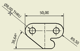
- Drag your cursor to position the leader and dimension for your hole callout. Click to finalize the placement.

Your drawing should now appear like Sheet:2 on the previously opened hinge.idw. Before you continue by working within a partially complete assembly drawing, save your drawing.
- With the drawing you created active, click Save As on the Application menu.
- Type a name for your drawing in the File name field of the Save as dialog box.
- Click Save. By default, your drawing is saved in the Inventor IDW drawing format.
If you routinely work with or send drawings to individuals using AutoCAD, consider saving your drawing in the DWG format.
- With the drawing you created active, click Save As on the Application Menu.
- Click the selection arrow on the Save as type field on the Save As dialog box.
- Select Inventor drawing files (*.dwg) from the drop-down list.
- You may want to change the name of the saved drawing or the location where you will save DWG files, but for this tutorial, simply click Save.
- From the Application Menu, click Close All.