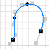
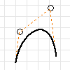
2D and 3D splines are curves of constantly changing radius. Inventor supports two types of splines, and provides a command to create each type: Interpolation, and Control Vertex. After you create a spline, you can change the type using the context menu.
Interpolation spline
Interpolation splines pass through a series of points, called fit points. For visual separation, spline endpoints are square, and spline fit points along the curve are diamond shaped.
To control how the spline data points are fit along the spline, you choose a Fit Method:
-
Standard
(default setting), or
Minimum Energy
You can manipulate the handles displayed in a passive state at each point to shape the curve. A 3D spline contains a tangent handle, but does not have curvature or flatness controls. Note: The spline tension control slider is available for all splines. Adjusting the spline tension automatically converts the spline to a Minimum Energy fit method.
- AutoCAD The spline does not have handles. Not suitable for creating class A surfaces.
You can partially or fully constrain spline points. Infer constraints to existing geometry as you draw the curve, or add constraints and dimensions later.
Handles for manipulating splines
Handles are available on splines you create with the Standard or Minimum Energy fit method. The tangent handle displays in a passive state at each fit point. A passive handle does not affect the spline shape.

You can manipulate the spline fit points or add dimensions to them without using the tangent handles.

You can apply constraints to handles to specify relationships to other geometry.
Control vertex spline
A control frame defines a control vertex spline. When you create the spline, the control frame displays as construction lines. Control vertices that influence the spline curves display as circles. You can adjust the shape of a spline by moving the control vertices.
You can constrain and dimension the spline endpoints, and the control frame, or you can constrain the spline itself.
You can drag the vertices or the lines of the control frame to change the shape of a spline. The results are often more predictable than when working with fit points in an interpolation spline.


Geometry offset from spline
The Offset command on the Sketch tab offsets geometry from an ellipse or trimmed ellipse. Use this technique to represent a uniform wall thickness.
When using Offset, the selection point on the ellipse determines the offset geometry type: a mathematical ellipse or an associative spline offset equidistant from the ellipse.
The Offset command has two default settings that affect the results of an offset ellipse:
- Loop Select chooses closed loops.
- Constrain Offset sets an equidistant constraint between the offset geometry and the original ellipse.
Curvature and smoothness of spline
Curvature is a mathematical indication of the smoothness between two curves or surfaces. The rate of change of direction is called curvature. The letter G, followed by a number, specifies the smoothness of a curve.
The continuity described in the following section is the result of joining two or more curves or faces. Constraints, or fillets smooth the transition.
- G0
- The endpoints touch. The transition between the two edges or surfaces is noticeable. The transition can be sharp or gradual
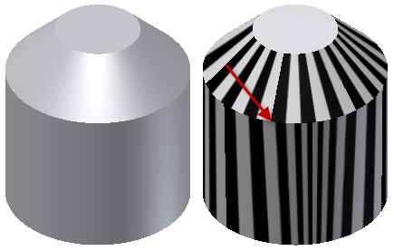
 . For example, a reflection in one surface disappears at the boundary and a different reflection appears in the next surface. In the following image, in a Zebra Analysis of a G0 intersection between two faces the faces meet, but no fillet exists to smooth the transition. The stripes do not line up, and there is an abrupt change between the faces.
- G1
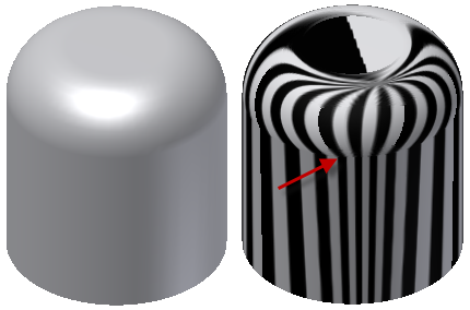
- G1 (tangent) continuity is a smooth transition between curves. The two curves or surfaces appear to be travelling in the same direction at the join, but the rate of curvature change (speed) is noticeable. For example, a reflection spans two surfaces, but there is a visible edge at the boundary. In the following image of a Zebra Analysis of a G1 intersection between two faces, a tangent fillet exists between the faces. The stripes meet, but the transition between the faces is sharp and angular.
- G2
- G2 (curvature) continuity is a smooth transition between curves. The two curves match at the endpoints, are tangent, and have the same "speed" (curvature) at the join. For example, a reflection appears in both surfaces with no obvious boundary. In the following image of a Zebra Analysis of a G2 intersection between two faces, a smooth (G2) fillet exists between the faces. The stripes meet, and the transition between faces is smooth, with no detectable boundary.
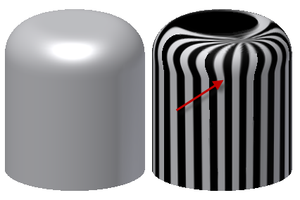
- G3
- G3 (curvature with constant rate of change) continuity is the same as G2, plus the rate of change in the curvature matches between the curves. This transition is smoother, with no detectable boundaries. Class A surfaces require G3 or higher continuity. For example, a reflection shows no detectable boundary changes between two surfaces with a high gloss finish in bright lights
Visualization of spline curvature
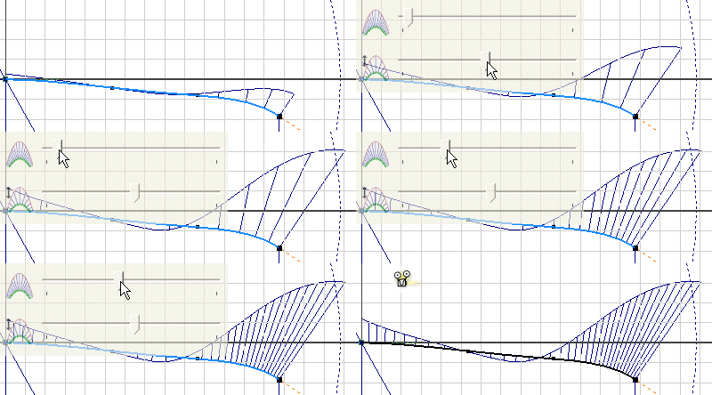
You can visualize spline curvature and overall smoothness. When you turn on Display Curvature, you turn on the curvature comb. It illustrates curvature with a series of connected spines that radiate outward from the curve. Longer spines indicate areas of higher curvature, and shorter spines indicate lower curvature. You can adjust the display of the spines in the Curvature Settings dialog box.
The length of each spine is equal to the curvature of the spline at that point, adjusted for the view scale. The progression of the tips of the spines indicates how continuous and smooth the curvature of the spline is.