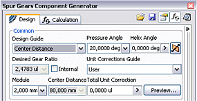
When you start the Spur Gears Component Generator, it opens on the Design tab. You can enter specific parameters, define spur gears placement, and select methods of calculation.
The Design tab is divided into several group boxes with options:
Common
This area includes parameters common for both gears, such as module or helix angle.
The Design Guide drop-down menu contains five possible options of design and calculation. Based on your selection of the design guide, the edit fields within the Design tab are enabled. Every method requires different input parameters.

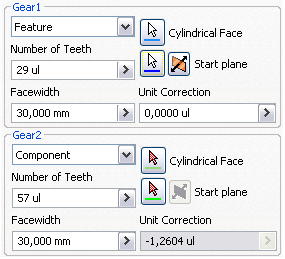
Gear 1, Gear 2
This area includes parameters that can vary for Gear 1 and Gear 2 such as number of teeth or face width. Also, commands for placement specification of Gear 1 and Gear 2 are located here.
Use the drop-down menu to select the type of gear to insert: component, feature, or no model.

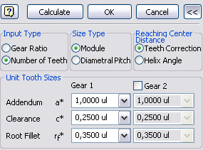
More Options
When you click the ![]() More options command, located in the lower-right corner of the Design tab, the area with other options for spur gears design opens. For example, if you select Number of Teeth in the Input Type group box, it indicates that number of teeth is a known value.
More options command, located in the lower-right corner of the Design tab, the area with other options for spur gears design opens. For example, if you select Number of Teeth in the Input Type group box, it indicates that number of teeth is a known value.

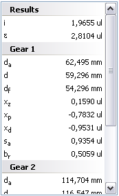
Results
Double-click the double line on the right, or click the chevron to display the Results pane with the list of calculated values. The values in gray indicate that results do not match the inserted values in the Design tab. Click Calculate to get results for current inputs.
