In this section, we will finish creating the 2D hinge clamp without leaving the assembly. The edit-in-place workflow allows you to project edges from other components into a sketch if necessary. You can also measure the available clearance before creating a solid.
We will then check the part for interference in the required range of motion.
To get started, drag the piston rod or the 2D sketch until the 2D sketch is in a near vertical orientation, as shown in the following image.
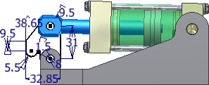
- Right-click the part Clamp Sketch in the browser and select Edit from the pop-up context menu, or right-click the 2D sketch in the graphics window and select Edit Component from the marking menu. You can also double-click the sketch or the part file in the browser to start an edit-in-place operation. Do not choose Open; if you do, the part file opens in a separate window.
The inactive assembly components appear transparent.
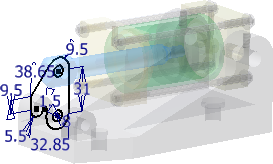
- Start the Extrude command. Enter a distance of 32 mm. Use the symmetrical in both directions option. Click OK to create the extrusion.
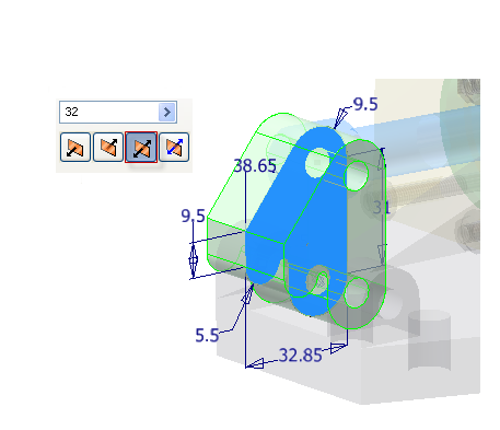
- To remove material from the solid to allow clearance for the piston, start a new 2D sketch on the front face of the clamp as shown in the following image.

- Project the geometry at the top of the extrusion to the sketch, as shown in the following image.
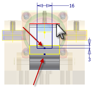
- Sketch a rectangle that is coincident with the projected line, as shown in the following image.
- Create a vertical constraint between the two edges indicated. Note: If your geometry does not match the following image after applying the constraint, undo and apply a horizontal constraint.
- Add a 16-mm horizontal dimension and a 3-mm vertical dimension, as shown in the following image.
-
 Finish the sketch.
 - Start the Extrude command. Cut the profile through the part. Use the All option.
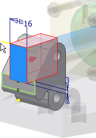
- Click OK to create the extrusion.
-
 Click the Return command, or right-click and select Finish Edit to return to the assembly environment.
 - On the ribbon, enable the
Inspect tab
 Interference panel
 Activate Contact Solver
command.
 - Move the clamp forward until the piston touches the front-end cap.
-
 Choose Analyze Interference. Select the piston rod to define set 1. Select the clamp to define set 2. Click OK to check for interference.
 A small interference is detected where the piston rod passes through the cut in the clamp.
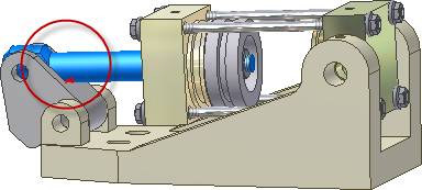
- To remove the interference, double-click the clamp hinge to initiate an edit-in-place operation. In the part browser, edit the sketch under Extrusion4, and increase the vertical dimension from 3 mm to 6 mm. Update the part, and return to the assembly. Check for interference again. The interference has been resolved.
- Save the assembly file and other components if prompted.