This exercise consists of two procedures: creating screw mounting bosses on the top and bottom bodies, and then creating mating bosses for the thread portion of the fasteners.
First, we use work points to model the screw mounting bosses on the top and bottom bodies.
- Turn on the Visibility of the bottom body and Work Points 1-4. The work points are located at the termination position of each boss.
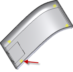
- On the ribbon, click
3D Model tab
 Plastic Part panel
 Boss
.
 - Make sure that the Head button is selected.
- On the Shape tab:
- In the Placement area, select On Point from the drop-down menu.
- Select the four work points as the Centers.
- For Direction, select the Y Axis. Flip the direction if the arrows do not point towards the body.
- For the target Solid, select the bottom solid.
- For Fillet, enter 0.3 mm.
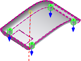
- On the Head tab:
- For Wall Thickness, enter 1.5 mm.
- For Shank Height, enter 1.5 mm.
- For Clamp Height, enter 0.5 mm.
- For Shank Diameter, enter 3 mm.
- For Clamp Diameter, enter 7 mm.
- For Head Diameter, enter 8 mm.
- For Draft Options, enter 2.5 deg in each field.
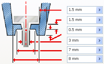
- Select the Counterbore type.
- Skip the Ribs tab.
- Click OK to create the four bosses.
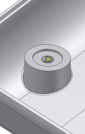
- Rotate the body to see the recess for the screw head.
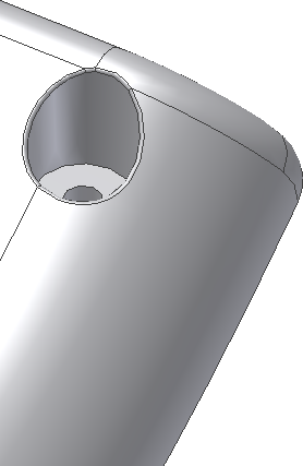
Next, we build the mating bosses for the thread portion of the fasteners.
- Turn off the Visibility of the battery cover and the bottom solid, and turn on the Visibility of the top solid.
- Click the Boss command.
- Make sure that the Thread button is selected.
- On the Shape tab:
- In the Placement area, select On Point from the drop-down menu.
- Select the four work points as the Centers.
- For Direction, select the Y Axis. Flip the direction if the arrows do not point towards the body.
- For the target Solid, select the top.
- For Fillet, enter 0.3 mm.
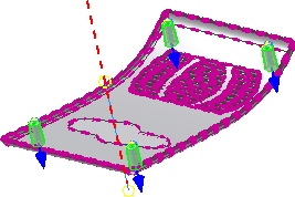
- On the Thread tab:
- Ensure that Hole is selected, and select Full Depth from the drop-down menu.
- For Thread Diameter, enter 8 mm.
- For Thread Hole Diameter, enter 3 mm.
- For Inner Draft Angle, enter 1 deg.
- For Outer Draft Angle, enter 2 deg.
- On the Ribs tab:
- Ensure that Stiffening Ribs is selected, and select 2 ul from the drop-down menu.
- For Rib Thickness, enter 1.5 mm.
- For Rib Draft, enter 1.5 deg.
- For Shoulder Length, enter 6 mm.
- For Top Offset, enter 2 mm.
- For Shoulder Radius, enter 1 mm.
- For Shoulder Flare Angle, enter 10 deg.
- Expand Fillet Options on the Ribs tab:
- For Rib Radius, enter 0.2 mm.
- For Blend Radius, enter 0.2 mm.
- For the Ribs Start Direction Angle, enter 0.
- For Direction, select the X Axis in the Origin folder.
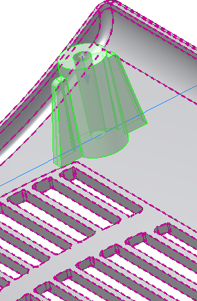
- Click OK to create the four bosses with stiffening ribs.
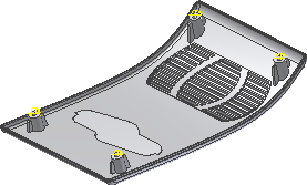
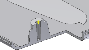
The following image shows a cutaway view of a boss.
- If you didn’t change the body appearances earlier in the exercise, right-click each body in the browser, and then select Properties from the context menu. Assign a unique body appearance in the Body Appearance drop-down menu.
- Save the file.
The plastic features portion of this tutorial is complete.