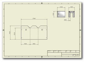
- Open the file 2mm_inplace_guard_start.idw, located in \Tutorial Files\Cylinder Clamp.Note: This drawing contains several views of a completed example guard that is supplied with the example tutorial files.
- On the ribbon, click
Annotate tab
 Table panel
 General
. The Table dialog box displays, and the view selection cursor is active in the graphics window.
 - Move your cursor over the view of the flat pattern until you see the dotted red view boundary highlight.

- Click to select the flat pattern view as the source view for the General table.Note: The General table type provides column selections unique to the type of source view selected. In this case, the table provides bend information.
- Click OK in the table dialog box to accept the default selections, close the dialog box, and place the table.
- Move your cursor over the upper-left corner of the drawing border. When your cursor changes to indicate a “point on” constraint, click to place the table.

A table is created with columns for Bend ID, Bend Direction, Bend Angle, and Bend Radius using the values for each of the bends in the selected view. Also, notice that the Bend ID numbers have been added to the flat pattern view near the bend centerlines.
The bend sequence identified is not likely to match the sequence your fabrication shop uses. Modifying the bend order sequence and adjusting the table is covered in the Sheet Metal Parts 2 tutorial.
Next, you place a punch table on the drawing.