In this portion of the tutorial, you create some simple sheet metal geometry and then apply styles to the part.
- Click the New icon
 , located at the top of the application window. Ensure that you click the icon itself, not the drop-down menu next to the icon.
 - In the Create New File dialog box, click the English folder, and then double-click the Sheet Metal (in).ipt template
 .
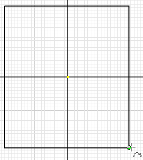
. - Sketch a rectangle approximately 10 inches square. The exact size and shape is not important.

- Click the Finish Sketch command on the ribbon, or right-click and select Finish 2D Sketch from the marking menu to exit the sketch.
- Click
Sheet Metal tab
 Create panel
 Face
Face
 . You can also right-click and select Face from the marking menu.
 - Accept the default dialog box settings, and then click OK.
Next, you add two flanges.
- Click the Flange command from the ribbon or the marking menu.
 .
. - Select two adjacent edges.

- Click OK.
The default template uses the default sheet metal styles. Next, you use Sheet Metal Defaults to apply the new styles to the part.
Tip: If you routinely use a certain style set, create a sheet metal part template that uses those styles by default.