- Double click manifold_block:1.
-
 Open the Parameters dialog box, and verify that the following parameter values are set as indicated.
Parameter Value block Tee component_type Standard port_a_size 0.50 - Save the assembly file.
Add Assembly Constraints
Assembly constraints restrict the movement of components relative to each other. Apply all constraints necessary to constrain each part fully and leave no degrees of freedom.
-
 Create Mate constraint port_a_cap_center between Port A and the manifold block. Use these selections:
 - The axis running through the center of Port A of the manifold block.
- The axis through the center hole of port_a_union.
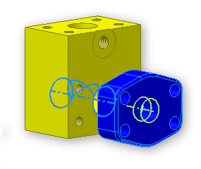 Note: If the union cap is hidden within the block after creating the constraint, click and drag the union cap away from the block.
 -
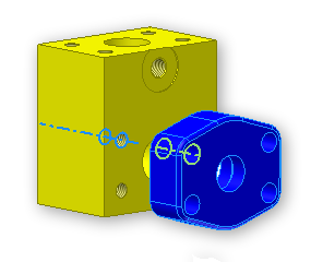
 Create Mate constraint port_a_cap_hole using these selections:
 - The axis running through the center of the Port A top left screw hole on the manifold block.
- The axis along the center of the top left screw hole of port_a_union.
-
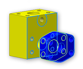
 Create Mate constraint port_a_cap_face using these selections:
 - The Port A face of the manifold block.
- The back face of port_a_union.
-
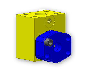
 Create Insert constraint port_a_cap_screw using these selections:
 - The port_a_union_screw
- The top left screw hole in port_a_union
- Follow the previous steps for Port B and Port C. Use similar names for the constraints.
Create Screw Patterns
Each port on the manifold block requires a pattern of four screws to attach the union cap to the block. Use the screw we inserted into the assembly as the patterned component.
First, create the screw pattern for Port A.
-
 On the ribbon, click
Assemble tab
 Component panel
 Pattern
.
 - click port_a_union_screw.
- Click the Rectangular tab.
- click the direction arrow in the Column area.
- click the bottom horizontal edge of the Port A face.
- Enter 1.50 for the horizontal distance.
- click the direction arrow in the Row area.
- click the left vertical side of the Port A face.
- Enter .69 for the vertical distance.
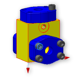
- Click OK.
- Rename Component_Pattern_1 in the Model browser to be port_a_screw_pattern.
Assign Descriptive Names to Pattern Parameters
When you create the screw component pattern, new model parameters are also created. Rename the parameters for future use in this tutorial.
-
 Open the Parameters dialog box.
 - click the name of the parameter containing 0.69 in the Equation cell.
- Change the parameter name to port_a_y_dist_between_screws.
- click the name of the parameter containing 1.50 in the Equation cell.
- Change the parameter name to port_a_x_dist_between_screws.
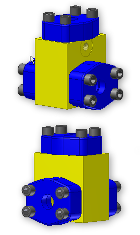
- Repeat the previous steps for port_b_union_screw and port_c_union_screw. Remember to rename the patterns when you are done. Your model should look as shown in these front and back views.
- Save your assembly file.