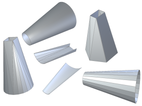
The Lofted Flange feature provides a way to create transitional sections in your model. They may be the only (or primary) feature in a model or they may be part of a more complex design.
The Lofted Flange feature requires the selection of two profile sketches. The profiles can be open or closed (or one of each) and can be on parallel or non-parallel sketch planes. The resulting feature can be optionally targeted at either a press brake or die-form manufacturing process.
- To begin this exercise, begin a new sheet metal part using the Sheet Metal (mm).ipt template.
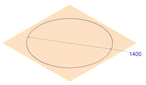
- In the open sketch, create a 1400-mm circle centered on 0,0.

- On the ribbon, click
Sketch tab
 Exit panel
 Finish Sketch
, or right-click and select Finish 2D Sketch from the marking menu.
 - Create a Work Plane offset (up) from the XY Origin Plane by 2000 mm.
- On this new offset Work Plane, create a 2D sketch.
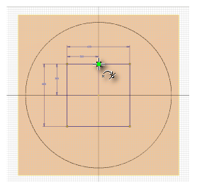
- In the sketch create a 600 mm x 600-mm square. Apply 300-mm dimensions so that the square is centered on 0,0.
- Place a point on the mid-point of one side of the square. Note: This point is not required for the Lofted Flange; however, you will use it later to create a Rip feature to flatten the Lofted Flange.

- Click
Sketch tab
 Exit panel
 Finish Sketch
, or right-click and select Finish 2D Sketch from the marking menu.
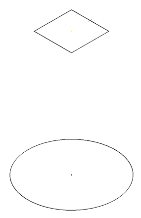
 - Hide the work plane that you created and the XY origin plane (if displayed). Hide the dimensions on both Sketch1 and Sketch2. Your model should appear as shown in the following image from the default Home View (F6).

Next, you create the Lofted Flange.