The Input Grapher provides a means of adding forces and torques that change during the simulation based on other independent variables.
We will add an external force that is dependent on the velocity in the prismatic joint between the Guide and Scottish Yoke. To provide a sense of the velocity we use + or - values to define an opposite force.
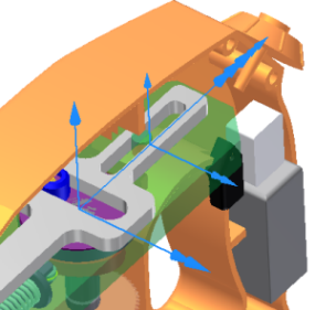
- In the browser, in Standard Joints, select the joint Prismatic (Guide:1, Scottish Yoke:1). Note that in the reference frames, when the velocity is positive, the reference frames point away from the blade end. If the reference frames point toward the saw blade, you may have to edit the joint to reverse the direction.

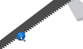
- In the Load panel, click the Force command. Select a vertex of one of the saw teeth.

- Click the Direction selector in the dialog box.
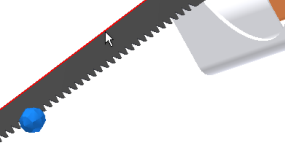
- Select the top edge of the saw blade that is parallel with the blade motion.

- Click the arrow on the Magnitude input control to display the list options, and click Input grapher.

The Input Grapher dialog box displays for the remaining steps.
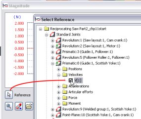
- Click the Reference selector, and in the Select Reference dialog box, expand Standard Joints > Prismatic (Guide:1, Scottish Yoke:1) to reveal the Velocities folder and contents. Click V(1) to specify velocity as variable for the graph X axis.

- Click OK. Notice in the graph region the X axis of the graph shows the reference you just specified.
When navigating inside the graph region.
- You can roll the mouse wheel, if you have one, to zoom in and out.

- To Pan the graph, click and drag the middle mouse button or wheel and watch the cursor move around the graph region.

- You can roll the mouse wheel, if you have one, to zoom in and out.
- In the lower section of the Input Grapher, for the Starting Point section, set X1 = -10 mm/s and Y1 = 250 N.
- In the Ending Point section, set X2 = -0.1 mm/s and Y2 = 250 N.
- Double-click in the graph area to the right and below the second point. This adds a new point, effectively creating a section in the graph.Note: You can also right-click beyond the second point and click Add Point to start a new section. To select the second section, click on the line between the points.
- The Starting Point for the second section (X1, Y1) is the previous section end point and is already set. To specify the second section Ending Point, set X2 = 0.0 mm/s and set Y2 = -250 N.
- Add a third section to the right of the second section. To specify the third section Ending Point, set X2 = 10.0 mm/s and Y2 = -250 N.
- Click OK to close the Input Grapher.
- Expand the dialog box and check the Display option at the bottom. You can also specify a different color to differentiate the force visually.
- Click OK to accept the input and close the Force dialog box.
- Run the simulation. Do not leave the Run environment.