In this task, you create cooling lines using a wizard then modify the cooling circuits created.
-
Click .

-
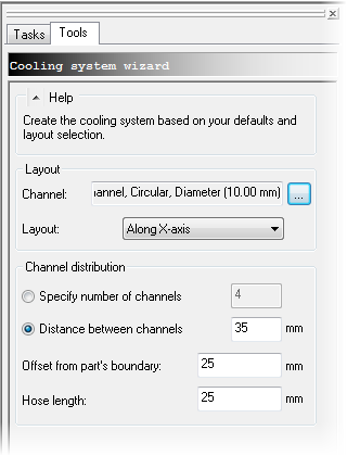
Ensure that the Channel diameter is 10 mm.
-
Ensure that the Layout is Along X-axis.
-
Click Distance between channels and specify a distance of 35 mm.
-
Enter an Offset from part's boundary of 25 mm.
-
Enter a Hose length of 25 mm.
-
Click OK.

-
Rotate the part to 0 0 0 so you can see the FRONT face of the View Cube.

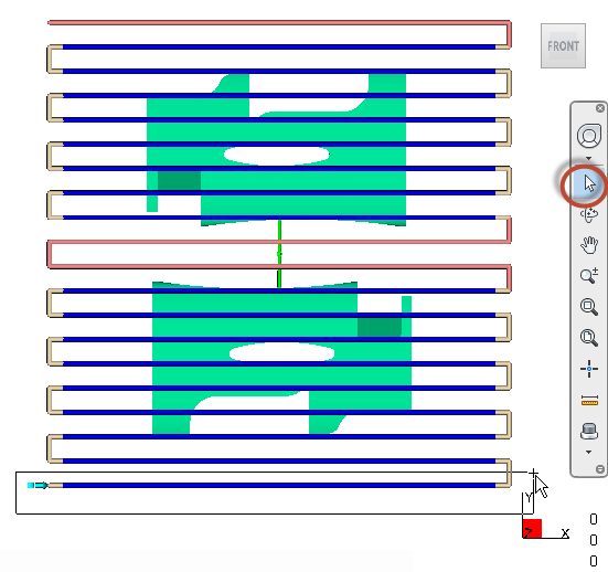
Notice how cooling channels (blue) are inside the mold outline, and hoses are on the outside.
-
Click .
-
Click off the Mold Outline.
-
Click to activate the Select tool from the Navigation Toolbar.
-
Select the two outermost and innermost channels and the hoses that connect to them, as shown. Hold the Ctrl key to select multiple items.

-
Press the Delete key. There are eight channels across each part, and two circuits, one each in the cavity and core. Now the circuits are split in two.
-
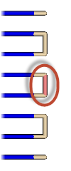
Select the middle hose for each cavity to split the circuits in two.

The eight circuits you create shown below.

-
Rotate the model so you can clearly see each circuit inlet and outlet.
-
Click .

-
Click the end of the hoses at the locations shown to create eight cooling inlets.
