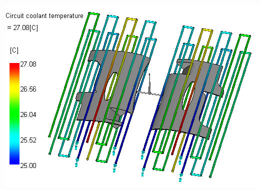
In this task, you interpret four different circuit results.
-
Click .
-
Ensure that the following objects are visible.
-
Cavities
-
Cooling Channels
-
Cooling Hoses
-
Cooling Inlets
-
-
If needed click to turn on the objects.
-
Rotate, pan, and zoom as necessary to see the circuit results.
-
Click Circuit coolant temperature in the study tasks list.
The increase in temperature is best when less than 2-3° C. Two cavity circuits are upper limit of the guideline indicating changes in the cooling design are desirable.

-
Click Circuit flow rate.
The input per circuit was 10 l/min. The pumping equipment needs a capacity of at least 80 l/min since there are 8 circuits.
-
Click Circuit Reynolds Number.
The results indicate the Reynolds number produced with the input flow rate. Typically a target of 10,000 Reynolds number is desired. In this case, the Reynolds number is well above this suggesting the flow rate could be lowered. However, if the flow rate is lowered, the coolant temperature rise in the circuits will go up. If you want to lower the flow rate, the circuits must be broken up to reduce their length.