The Project panel displays information about the model that is being analyzed.
Ensure the study used in the previous task is open. Alternatively, open tutorial_model from the Getting Started project you created in the Importing a model tutorial.
The Project panel is located in the upper left of the user interface.
If this panel is not displayed, it can be accessed by clicking  and checking Project and Study Tasks.
At the top of this panel are two tabs, the Tasks tab and the Tools tab.
The Tasks tab
There are two sections to the Tasks tab
-
Project View pane
The Project View pane is the upper section of the Tasks tab. This is where the studies in the current project are listed. The icons to the right of the study name are analysis icons and these will be discussed in a later tutorial.
The pane you are displaying shows that the current project is Getting Started and the only study currently available is tutorial_model (the study you originally imported).
-
Study Tasks pane
The Study Tasks pane is the lower section of the Tasks tab and this is where details about your active study are displayed. The status of the tasks required before analysis and the results generated are also shown.
The Tools tab
The Tools tab is the second tab of the Project panel.
Models usually require some manipulation of geometry or definition of features prior to analysis. The modeling dialogs open in the Tools tab.
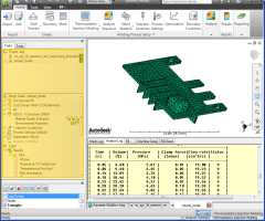
- From the Results section of the Study Tasks pane, tick Fill Time for a visual representation of the time required to fill the mold.
- Rotate the model to investigate this result.
- Experiment with the other analysis results that are available.
- Click
 () to open the Mesh tab.
 - Click
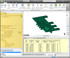
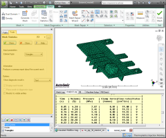
 (). The Aspect Ratio Diagnostic dialog opens in the Tools tab. This feature is explained in the meshing tutorial.
 - Ensure the Minimum Input parameter is the default of 6.
- Tick the Place results in diagnostics layer option.
- Click Show.
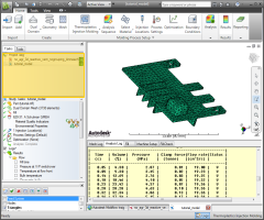
- The lines that appear in the Model pane indicate the location of elements with an aspect ratio greater than 6. The color of the line indicates the magnitude of the issue.
- Rotate and zoom into sections of the model to investigate the elements with a high aspect ratio. will revisit these results in the Layer panel task.
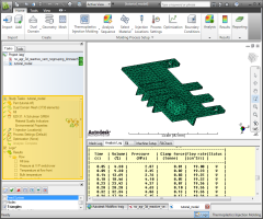
- Right-click on the model and select
 Mesh Diagnostics to remove the lines.
 - Return the model to its original orientation as outlined in the Model manipulation task. Using the
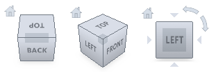 ViewCube, select Front and then click
  ().
().
Click the Next topic link below to move on to the next task of the tutorial.