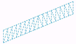
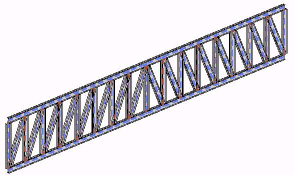
In Revit, you can add a truss to your building model. Use the Truss tool, which creates the truss according to the layout and other parameters specified in the truss family type you select. For information about creating a truss family, see Creating a Truss Family.
The lines in the layout determine the placement of the sub elements that comprise the truss element, such as the top chord, bottom chord, and web members.
All types within a truss family share the same layout. Individual types specify other parameters, such as the structural framing families to be used for modeling chords and web members.
To use the Truss tool, select a truss family type and then specify the truss start point and endpoint in the drawing area. Then Revit creates structural framing elements as necessary, placing them on the layout lines specified for the selected family.


You create structural framing elements along each of these layout lines. You can define the structural framing elements in the truss layout family. Several different types of the same family can have different pre-set framing families using the same geometric layout.
