Joule heating is the generation of heat by passing an electric current through a metal. Also known as resistance heating, it simulates heating in electrical resistance heaters and stove-top burner elements. Inputs include current, voltage, and the material resistivity.
Joule Heating Setup
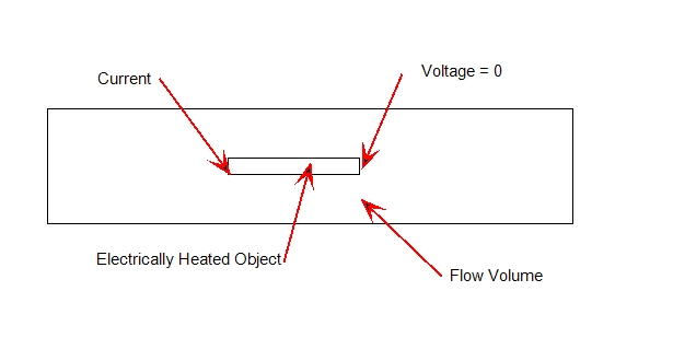
Two boundary conditions are available to define a Joule heating condition: Current and Voltage. The typical way to define the loading is to assign a current on one end of the solid through which electricity is passing and a voltage of 0 on the other end:

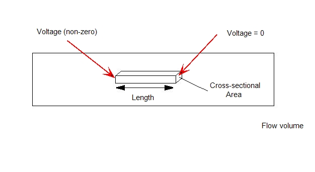
Alternatively, a potential (voltage) difference can be applied across the device by specifying a non-zero voltage on one end and a zero-value voltage on the other. In this case, the current boundary condition is omitted.

The Resistivity material property is the product of the resistance and the cross-sectional area divided by the length of the part. A value for resistivity is required for any solid that is heated by the Joule effect.
The relationship between resistivity and resistance

- r = resistivity (ohms-length unit)
- R = resistance (ohms)
- L = length of the device
- A = cross sectional area
A non-zero value for resistivity should always be specified for solids undergoing Joule heating.
A non-zero value for resistivity should always be specified for solids in which Joule heating occurs. To simulate insulative (non-conductive) materials in a Joule heating simulation, apply a resistivty value that is 1000 times greater than the smallest specified resistivity in the model. By default, such a material is considered to be an insulator, and is not thermally affected by electric current.
To simulate a resistivity that is greater than this default threshold, enable this flag, and specify the desired ratio. Joule heating is computed in solids with resistivity values that do not exceed this value.
max_electrical_resistance_ratio A
The argument, A, is the threshold resistivity ratio at which a part is considered insulative. For example, to compute Joule heating effects in a material that has a resistivity 10000 times greater than the smallest specified resistivity in the model, enable this flag, and assign a value of 10000.
As with any heat transfer analysis, a temperature needs to be specified somewhere in the model (either as a temperature boundary condition or as a surrounding temperature for a film coefficient boundary condition).
Mesh objects heated by the Joule effect with at least two layers of elements across the cross-section. This will ensure that there are enough nodes to resolve the temperature gradients across the device.
Joule heating is invoked automatically if the Current and Voltage Boundary Conditions and the Resistivity Material Property are set. Additionally, heat transfer must be enabled on the Solve task dialog. There is not a separate button to invoke Joule Heating.
A useful technique is to hand-calculate the temperature differential based on the resistivity, applied current, and dimensions of the object. To do this:
- Begin by computing the resistance, R, of the object using the length, L, Area, A, and the resistivity, r:

- Next use the Voltage, V, and the Resistance to compute the current, I:
V = I x R
- Calculate the dissipated power, P:

- The temperature differential is then computed using the power, length, area, and thermal conductivity, K:

This will provide an estimate of the temperature change that will occur as a result of Joule heating. It is recommended to compute the temperature change as a reality check to ensure that the specified values are physical and reasonable.
Simulating Joule Heating in a Fluid
Joule Heating in Autodesk Simulation CFD is designed primarily to simulate electrical resistance heating in solid objects. However, there are some situations in which a fluid acts as a current path, and is subject to Joule heating. To simulate the heating effect of current passing through a fluid:
- Compute the electrical power through the fluid using the following equation:

- Assign the resultant power as a volumetric heat generation to the fluid.
Related Topics