The software allows the user to check allowable stresses versus the Allowable Stress Design (ASD) code checking Specification for Structural Steel Buildings from the American Institute of Steel Construction (AISC) 9th Edition (1989).
The general steps for performing a beam code checking analysis are as follows:
- Create an analysis that includes beam elements. The following analysis types are supported:
- Linear (Static Stress with Linear Material Models, Response Spectrum, and so on)
- Nonlinear (MES with Nonlinear Material Models, and so on) that use a material model of Linear, Isotropic, or von Mises with Isotropic Hardening.
- Code checking is done on the beam elements whose cross section is either from the AISC 2001 (or newer) database or a user-defined shape (wide flange, C channel, pipe, or hollow rectangle). (The cross section is entered in the Element Definition dialog.) Also see the General Assumptions below for other restrictions.
- The beam material properties need to include the yield stress. The yield stress is only used in the calculation of the allowable stress; it is not used to calculate plasticity and does not affect the calculation of the stress or deflection.
- Perform the analysis.
- In the Results environment, set up the code checking parameters (see below).
- Review the code checking results. This can be done graphically or by generating reports (see below).
Set Default Parameters
After the analysis is completed and the model is in the Results environment, the code checking parameters should be set.
The AISC code requires the usage of the effective length factor, K, which helps the engineer account for various kinds of end conditions (pinned, fixed and so on). This factor needs to be specified for each member in both directions. By default it will be assumed a value of 1 for Kx and Ky.
The AISC code requires the constant, Cm, that is specified on a per member basis. It is assumed to be a default value of 0.85.
These defaults can be changed individually using Results Contours  Stress Beam Code Checking Setup to access the Member Properties dialog. Select the appropriate entry in the spreadsheet and change the value. To change the value for all the members, press the Set Defaults button. After changing the defaults and clicking OK to close the dialog, clicking the Reload Using Defaults button will populate the table with the new current defaults.
Also, when a row is selected in the Member Properties dialog, all beam elements in the model that comprise the selected member will be highlighted in the model.
Define Members
During code checking, multiple beam elements are combined into members, where the length of each member is used in the allowable stress calculations. The lengths for bending about the weak axis and about the strong axis are separate values.
The creation of members is done in the Results environment. The following outlines how these are created. The code checking calculations are computed based on the group of beam elements in the members, not the individual beam elements.
Two adjacent beam elements are considered to be part of one member if:
- They are in the same part.
- They have the same cross section.
- They are colinear.
- There are no beam end releases or offsets at the common node.
- There are the only 2 elements (of any type) coming together at the common node.
- There are no boundary conditions or boundary elements applied at the common node
If any of these conditions are not met, a member would be terminated and the next element would start in a new member.
Once members are constructed, the Results environment will assume that the length of the member (L) is the total length of the adjacent elements. When computing actual stresses in the member, the Results environment will examine results for the 2 nodes of each of the beam element that comprise a member. The allowable stress values will be computed in compliance with the code. The largest result would then be treated as applicable to all elements that comprise the member.
-
- Although the members (and their associated lengths) are calculated automatically, the user can change the weak axis length, strong axis length, or both using either of these methods:
- Select the members whose length are to be combined (Selection Select Beam Members) in the display area. Right-click and choose the appropriate command. In each case, the length currently entered in the Member Properties spreadsheet is used in the summation.
- Combine Strong Axis Lengths will set the length for bending about the strong axis for all the selected members to the sum of the lengths from each member.
- Combine Weak Axis Lengths will set the length for bending about the weak axis for all the selected members to the sum of the lengths from each member.
- Combine Both Lengths will set the length for bending about the strong axis and weak axis for all the selected members to the sum of the respective lengths from each member.
- From the Member Properties dialog (Results Options: Beam Code Check Setup), click the cell for the length to change and enter a new number.
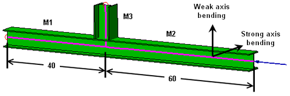
Figure 1: Example Beam Structure
- Select the members whose length are to be combined (Selection
Note:- Once a member has been combined using the select, right-click, Combine Lengths method described above, none of the individual members can be used to combine the lengths with other members. (The strong axis and weak axis lengths are treated separately.) Attempting to do so will result in a warning The requested operation was not completed because some of the members selected are already combined with other members.
- For example, if you intended to combine the weak axes of members M4, M5, and M6 but only had M4 and M5 selected, you will not be able to select the combined M4/M5 members and M6, right-click, and choose Combine Weak Axis Lengths. What you can do is manually change the length entries in the Member Properties dialog for M4, M5, and M6. Alternatively, you can use the Reload Using Defaults button which will reset the list of combined members, but this will reset everything in the table.
- The lengths should be changed after changing the other default values. (See above.) Since the lengths are an input, the change in length due to tension or compression is not taken into account, even in a nonlinear, large displacement analysis.
- Although the members (and their associated lengths) are calculated automatically, the user can change the weak axis length, strong axis length, or both using either of these methods:
View Results
The Results Contours Stress Beam Code Checking contains seven commands that can be used to display the ratio of the calculated stresses to the allowable stress for the material per the selected code.
- Strong Axis Slenderness Ratio: This will display the slenderness ratio about the strong axis. The slenderness ratio calculation is described in the code section.
- Weak Axis Slenderness Ratio: This will display the slenderness ratio about the weak axis. The slenderness ratio calculation is described in the code section.
- Strong Axis Bending Ratio: This will display the ratio of the bending stress about the strong axis to the allowable stress.
- Weak Axis Bending Ratio: This will display the ratio of the bending stress about the weak axis to the allowable stress.
- Local 2 Shear Ratio: This will display the ratio of the shear force in the local 2 direction to the allowable.
- Axial Stress Ratio: This will display the ratio of the axial stress to the allowable stress.
- Worst Ratio: This will display the ratio of the worst stress to the allowable stress, based on the appropriate combination of axial, strong axis bending, and weak axis bending.
Generate Reports
In addition to the results contours that can be displayed (and put into a report if necessary), the following types of text reports can be created specifically for the code checking:
- Single Load Case or Single Time Step: This code checking report uses the results from the current load case or time step. The report will summarize the results for all members (member lengths, stress ratios, and so on) with red highlighting used to identify failed members. This report can be generated from Results Contours Stress Beam Code Checking Setup, then Generate Report Current Load Case or Current Time Step. The report header indicates which load case/time step was used for the report.
- All Load Cases or All Time Steps: This code checking report uses the results from all load cases or time steps. The report will summarize the results for all members (member lengths, stress ratios, and so on) with red highlighting used to identify failed members. The load case number (LC) or time step number (TS) the results are from is given where appropriate. (It is possible that different results are maximum in different load cases or time steps.) This report can be generated from Results Contours Stress Beam Code Checking Setup, then Generate Report All Load Cases or All Time Steps.
- Detailed: This code checking report uses the results from the current load case or time step for the selected member. The report will provide great detail for the member, such as the comprising beam element numbers, the comprising results and the equation numbers of the failing/passing formulae used, and so on. To generate a detailed report, go to Results Contours Stress Beam Code Checking Setup, then right-click in the row for the member for which you want the detailed report and select the Generate Detailed Report command. The report header indicates which load case/time step was used for the report.
When a report is created, the Report environment is automatically launched and displays the report. Once in the Report environment, any of the generated reports can be viewed by selecting the entry in the tree view. (The Configure Report dialog can be used to include or exclude each of the code checking reports from the overall report.)
General Assumptions
1. Only the following structural shapes are considered. AISC library refers to the AISC 2001 (or newer) database:
- I-Shaped members from the AISC library: W, M, S and HP or user-defined Wide Flange Beam
- Channels from the AISC library: C, MC or user-defined C Channel
- Angles from the AISC library: L
- Structural Tees from the AISC library: WT, MT, ST
- Pipes from the AISC library or user-defined Pipe
- Structural tubing from the AISC library: HSS or user-defined Hollow Rectangular
2. The following are not considered:
- Built-up members - hybrid beams
- Transverse stiffeners
- Plate girders (web slenderness ratio h/tw above the limit of 970/sqrt(Fy))
- Double angles
- Plates
3. All loadings are assumed to be symmetrical about either the strong or the weak axis.
4. Flanges are continuously connected to webs for I-shaped section.
5. Structural tubing has uniform wall thickness.
6. Torsion effects are not considered.
7. Many AISC ASD code checking formulae especially those which apply to beams under axial compression require us to know the unbraced length of the flange. Quite possibly depending upon the boundary conditions (constraints), a member can have different unbraced lengths that allow bending about the 2 axes.
8. The user has applied the loads in accordance with the code's specification. The code checking software does not check that the model meets the specifications except as documented.
Also refer to the following page, Allowable Stress, for the formulas used in the code checking.