While the software automates many of the parameters related to surface-to-surface contact, some models will benefit from adjustments by the user. This page summarizes many tips that can improve the Mechanical Event Simulation and nonlinear stress model runtimes when contact is included.
Proper Meshes
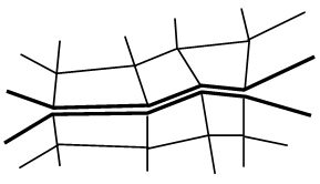
To perform an accurate contact analysis, a reasonably smooth contact surface and a uniform mesh over the contact surfaces are highly recommended. Furthermore, since surface mesh alignment can impact the performance of the whole analysis, surface meshing on each adjacent contact surface should be carefully done to achieve a better convergence rate. In linear contact, the mesh on the two surfaces should be perfectly matched to each other as shown in Figure 1 (a). However, in MES, a perfectly matched mesh could cause severe contact chattering. When this chattering occurs, it inevitably results in a very poor convergence rate (longer runtime). To avoid or at least minimize this problem, when small relative motion between the contact surfaces is expected, it is recommended that the mesh should have the nodes on one surface located in the middle of the nodes on the other surface as shown in Figure 1 (b). (Exception: If using Point to Point contact type, then the meshes must match-up. However, Point to Point is based on no relative motion of the nodes. See Surface-to-Surface Contact Options for details.) For meshes on CAD models, use the Prevent part matching option described on the page Meshing Overview: Meshing CAD Solid Models: Model Mesh Settings: Model.
|
(a) In linear stress, the mesh must match for proper contact
(b) In MES, the mesh should not match when using surface-to-surface or point-to-surface contact, especially if there is small relative motion. |
| Figure 1: Proper Mesh for Contact Analysis |
Iterative Schemes
The processor provides six types of nonlinear solution schemes (on the Setup Model Setup Parameters Advanced Equilibrium tab) to control the iterative solution process: modified Newton-Raphson, full Newton-Raphson, combined Newton-Raphson, and these three options with line search. It is difficult to say which one is the best choice. However, full Newton-Raphson with or without line search is strongly recommended for a contact analysis to converge with the fewest number of iterations.
Use Constraints to Stabilize Models
Although it may be realistic to leave parts free to fly around and come into contact, some models can be improved by partially restraining the parts. For example, a pin passing through a yoke and clevis is free to rotate in reality, but will not usually rotate because there is no force to cause the pin to rotate. In this situation, applying constraints to prevent the pin from rotating can reduce the contact chattering (oscillating between contact with adjacent elements) that may occur if the pin tries to rotate. Likewise, the axial motion of the pin may be insignificant, so constraints to prevent axial motion can reduce the runtime.
Convergence Rates
Watch the Residual value (last column of the analysis log) during model execution. If the solver seems to be reducing the time step size unnecessarily (even though the residual is decreasing and the solution seems to be progressing towards convergence), change the Decrease trigger rate of convergence setting from Automatic to Avoided. This setting is found under the Setup Model Setup Parameters Advanced Time-step tab. Similarly, if the solution is progressing towards convergence but reduces the time step due to reaching the specified maximum number of iterations (default = 15), try increasing the number of iterations. It is better to allow some more iterations than to divide the time step and start the iteration process over again. This setting is found under the Equilibrium tab of the Analysis: Parameters: Advanced dialog.
Automatic Settings or Not
The most difficult step in contact analysis is determining the proper contact parameters. When the user chooses the Automatic setting for a contact parameter, the processor calculates an appropriate value based on the initial contact surface geometry, the mesh and material constants. However, this default value may not be valid after the bodies undergo large deformation. When the contact part is expected to experience large deformation, the user should consider these items before starting the analysis and determine an appropriate value.
Contact Stiffness
A rule of thumb is to use a contact stiffness of one-tenth the modulus of the softer material. When a very soft material is in contact with a stiff material (for example, foam against metal), the one-tenth rule and stiffness calculation equation might fail in providing a proper value and cause serious contact chattering or large penetration. Even using the adaptive contact stiffness scheme, poor convergence is inevitable until a proper stiffness value is found after several iterations. In such cases, the user needs to explore some test cases with a simple 2D contact model using the same material and loading conditions. Simply test several contact stiffnesses, increasing (or decreasing) it by a factor of 10 from a relatively small number compared to the Young’s modulus of the soft material until the smallest value that does not allow large penetration has been found. When the first test has been completed, check the convergence rate by simply counting the number of iterations. If the global convergence is not good and there is no large penetration, the stiffness value could be too large and needs to be reduced and tested again.
See the section General tab on the page Surface-to-Surface Contact Advanced Controls for details.
Contact Type
There are three levels of contact in surface-to-surface contact. Each one considers more details about what contact is detected. Based on the anticipated motion and shape of the parts, the user may be able to select a contact type that gives a faster solution than using the automatic setting. In summary, the contact types are as follows:
- Point to Point: Only the nodes can contact each other. Otherwise, a node on one body can pass through the surface of the other body.
- Point to Surface: The nodes on the secondary part can contact the surface of the primary part. But, the nodes on the primary part can pass through the surface of the secondary part. (This could be thought of as one-way contact detection.)
- Surface to Surface: The nodes on the secondary part can contact the surface of the primary part, and the nodes on the primary part can contact the surface of the secondary part. Thus, this is the most complete level of contact detection but requires more calculations.
Relatively small deformation is assumed when computing the contact parameters (except for the adaptive contact stiffness and contact group updating). When contact surfaces undergo large displacement or large deformation, such as more than 50% strain even in the localized area, the basic assumption used in calculating contact parameters (master and target surfaces, contact type and contact extend area) may no longer be valid. The user may need to consider the deformed shape ahead of time and then choose the parameters.
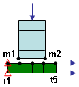
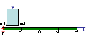
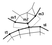
Figure 2 shows that situation in which the automatic setting may fail. Considering the initial geometry, point-to-surface contact appears to be a proper choice because the segments on the master surface (the first part/surface) are much larger than the segments on the target surface (the second part/surface). However, after the target part deforms, the segment size of the target surface becomes bigger than the master surface. This leads to a situation where segment m1-m2 fails in to detect any target node and leads to lost contact and penetration of the target surface. In this circumstance, surface-to-surface contact is highly recommended.
See the page Surface-to-Surface Contact Options for details.
|
(a) Based on original geometry, point to surface contact type is acceptable (points are target nodes, t1-t5 contact the surface of master nodes, m1-m2).
(b) After deforming, no nodes on the target surface (t1-t5) make contact with the surface of the master (m1-m2). The contact type of surface-to-surface is required because of the deformation. |
| Figure 2: Automatic Selection of Contact Type Fails Due to Large Deformation |
Extend Contact Sides
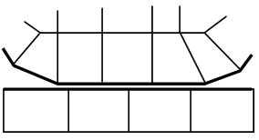
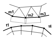
Regarding the extension of the contact area, when the initial contact surface is flat or has low curvature, the automatic setting to calculate the areas of extended contact produces a small extension. When the part deforms, the contact areas may open up, leaving a ghost area or hole in the contact in which the contact with the target node is not detected. See Figure 3.
|
(a) Based on original geometry, extend contact element sides is set to some value on the master surface (m1-m2-m3). (Contact surface shown by dotted lines.)
(b) After deforming the master surface (m1-m2-m3) to create a sharp curvature, the extend contact sides is too small to prevent a node on the target surface (t3) from getting stuck in the ghost area between the contact sides. |
| Figure 3: Automatic Selection of Extend Contact Sides Due to Large Deformation |
When a contact surface has many sharp edges and large sliding motion, the Extend contact element sides value plays a very important role in convergence. See the section Geometry tab on the page Surface-to-Surface Contact Advanced Controls for details.