Brick elements are four-, five-, six- or eight-node elements formulated in three-dimensional space. Brick elements are used to model and analyze objects such as wheels, flanges, and turbine blades. Brick elements have the ability to incorporate midside nodes (producing 21-node elements) and several material models.
When applying loads to a surface number of a brick part, be aware that some models may not have all the lines on the face to be loaded on the same surface number. What happens in this situation? If the model originated from a CAD solid model, all faces coincident with the surface of the CAD model receives the load regardless of the surface number of the lines. In hand-built models and on CAD parts that are altered so that the part is no longer associated with the CAD part, the surface number that is common in any three of the four lines that define a face (four-node region) or two of the three lines (three-node region) determines the surface number of that face.
Brick elements, by definition, cannot have rotational degrees of freedom (DOFs). You can apply translational DOFs as needed.
Several geometries of the brick element are available for structural analysis. These element versions have 4, 5, 6, 7 and 8 nodes available.
These 4- to 8-node elements are formulated in 3D space, and have only three degrees-of-freedom defined per node: the X translation, the Y translation and the Z translation. Incompatible displacement modes are available only for 8-node elements. Pressure, thermal and inertial loads in three directions are the allowable element based loadings. You may also use centrifugal and nodal loads.
|
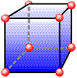
Figure 1: 3D Brick Element, 8-node |
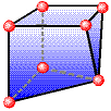
Figure 2: 3D Brick Element, 7-node |
|
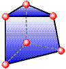
Figure 3: 3D Brick Element, 6-node |
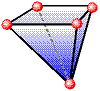
Figure 4: 3D Brick Element, 5-node |
|
Figure 5: 3D Brick Element, 4-node |

The elements with less than 8 nodes are known as hybrid elements. They serve as transition elements between 8-node bricks and other elements such as tetrahedrons.
When to Use Brick Elements
- The stress results through the thickness of a part is needed.
- The model has only forces applied, no moments. (Bricks have no rotational degrees of freedom). For advice on how to apply a moment to a brick, see Meshing Overview: Creating Contact Pairs: Examples of Contact.
- The model has a hydrostatic pressure load applied.
- To capture bending in models with brick elements, three elements should be created through the thickness. If this cannot be done for the model and is needed, the model may need to be evaluated using plate elements.
Brick Element Parameters
- If the material properties in all directions are identical, select the Isotropic option.
- If the material properties vary along three orthogonal axes, select the Orthotropic option.
- If the material properties vary with temperature, select either the Temperature Dependent Isotropic or Temperature Dependent Orthotropic option.
- If you are performing a voltage induced stress analysis, select either the Piezoelectric or General Piezoelectric option.
- To define the material properties by specifying the stiffness matrix, select the Anisotropic option.
- If the part is injection molded, the anisotropic material properties that result from the molding process can be obtained from an Autodesk Moldflow simulation. Select Moldflow as material model. See Interoperability with Autodesk® Simulation Moldflow® for details.
When using brick elements, you must specify the material model for this part in the Material Model drop-down menu.
The next parameter that can be defined is the compatibility. This is done in the Compatibility drop-down menu. See Incompatible Displacement Modes for more information.
- If the Not Enforced option is selected, gaps or overlaps is allowed along inter-element boundaries. These elements are formulated using an assumed linear stress field. These elements are most effective as low aspect ratio rectangles. The Compatibility: Not Enforced only applies to 8-node elements. The other configurations (6-, 5-, and 4-node elements) are always Compatibility: Enforced.
- If the Enforced option is selected, overlaps or discontinuities are not allowed along inter-element boundaries. These elements are formulated using an assumed linear displacement field. These elements can overestimate the stiffness of the structure. In general, a greater mesh density in the direction of the strain gradient is required to achieve the same level of accuracy as elements for which the Not Enforced option is selected.
If you want the brick elements in this part to have the midside nodes activated, select the Included option in the Midside Nodes drop-down menu. If this option is selected, the brick elements have additional nodes defined at the midpoints of each edge. (For meshes of CAD solid models, the midside nodes follow the original curvature of the CAD surface, depending on the option selected before creating the mesh. For hand-built models and CAD model meshes that are altered, the midside node is located at the midpoint between the corner nodes.) It changes an 8-node brick element into a 20-node brick element. An element with midside nodes results in more accurately calculated gradients. This is especially useful when trying to model bending behavior with few elements across the bending plane. Elements with midside nodes increase processing time. If the mesh is sufficiently small, then midside nodes may not provide any significant increase in accuracy.
 Model Setup Parameters dialog box. (The location under the Analysis Parameters varies from analysis type to analysis type.)
 Next, select the integration order that is used for the brick elements in this part in the Integration Order drop-down menu. For rectangular shaped elements, select the 2nd Order option. For moderately distorted elements, select the 3rd Order option. For extremely distorted elements, select the 4th Order option. The computation time for element stiffness formulation increases as the third power of the integration order. Consequently, the lowest integration order which produces acceptable results should be used to reduce processing time.
When you use a Moldflow material model, use the Residual Stress (Moldflow Insight Only) drop-down to include or exclude residual stresses for your analysis. If set to Include, stresses built-up during the injection molding process are modeled. Upon ejection from the mold, the part shrinks and warps to redistribute the stresses incurred while in the mold. Your model part represents the in-mold dimensions.
If you are performing a thermal stress analysis on this part, specify the temperature at which the elements in this part experiences no thermally induced stresses in the Stress Free Reference Temperature field. Element based loads associated with constraint of thermal growth are calculated using the average of the temperatures specified on the nodal point data lines. The reference temperature is used to calculate the temperature change. Thermal loading may be used to achieve other types of member loadings. For these cases, an equivalent temperature change (dT) is used.
Control the Orientation of Brick Elements
If this part of brick elements is using any material model except for isotropic or temperature dependent isotropic, you will need to define the orientation of material axes 1, 2 and 3 in the Orthotropic tab of the Element Definition dialog box. There are two basic methods to accomplish this.
Method 1:
The first method is to select one of the global axes as material axis 1. If you select the Global X-direction option in the Material axis direction specified using drop-down Menu, the orthogonal material axes follows the X, Y and Z axes:
- Material axis 1: X axis
- Material axis 2: Y axis
- Material axis 3: Z axis
If you select the Global Y-direction option in the Material axis direction specified using drop-down menu, the orthogonal material axes follows the X, Y and Z axes:
- Material axis 1: Y axis
- Material axis 2: Z axis
- Material axis 3: X axis
If you select the Global Z-direction option in the Material axis direction specified using drop-down menu, the orthogonal material axes follows the X, Y and Z axes:
- Material axis 1: Z axis
- Material axis 2: X axis
- Material axis 3: Y axis
With the first method, the axes can be rotated about the chosen global direction by entering an angle in the Material Axis Rotation Angle field. This angle follows the right-hand rule.
Method 2:
The second method is to select the Spatial Points option in the Material axis direction specified using drop-down menu. Next you must define the coordinates for three spatial points in the Spatial point coordinates table. Next, select the appropriate index for the spatial points in the Index of spatial point 1, Index of spatial point 2, and Index of spatial point 3 drop-down menus.
- Material axis 1 is a vector from the spatial point in the Index of spatial point 1 drop-down menu to the spatial point in the Index of spatial point 2 drop-down menu.
- Material axis 2 is perpendicular to local axis 1, lies in the plane formed by the three spatial points, and is on the same side of axis 1 as the spatial point in the Index of spatial point 3 drop-down menu.
- Material axis 3 is calculated as the cross-product of material axes 1 and 2.
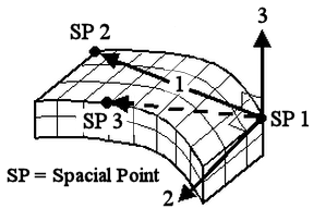
Figure 6: Orientation of Material Axes
To Use Brick Elements
- Be sure that a unit system is defined.
- Be sure that the model is using a structural analysis type.
- Right-click the Element Type heading for the part that you want to make brick elements.
- Select the Brick command.
- Right-click the Element Definition heading.
- Select the Edit Element Definition command.
- Select the appropriate material model in the Material Model drop-down menu. There are six model choices. For more information on these models, see Material Properties.
- To have midside nodes used in this part, select the Included option in the Midside Nodes drop-down menu.
- If you are performing a thermal stress analysis, enter a temperature into the Stress Free Reference Temperature field. The difference between this value and the applied temperatures is used to calculate the stress
- If you are using either an isotropic or temperature dependent isotropic material model, press the OK button.
- If you are using any other material model, click the Orthotropic tab.
- Decide how your material axes is oriented by selecting the proper choice in the Material axis direction specified using drop-down menu.
- Press the OK button.