Once again, refer to the Beam Tower drawing below for the angle orientation and the beam endpoint coordinates.
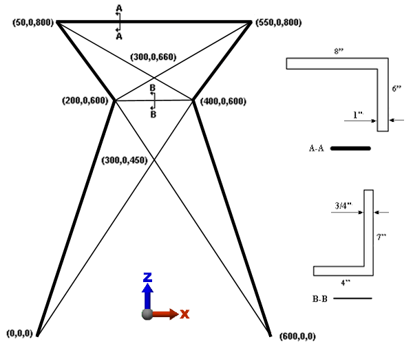
Next, we will draw the beam elements that represent the 7x4 angle. For these beams, the local 2 (weak bending) axis will lie in the XZ plane (perpendicular to the global Y direction) as shown by the orientation of Section B-B. A beam orientation point in the +Z direction, relative to the origin, will correctly orient the cross-section for all of these angles. In Autodesk® Simulation, beams on Surface 2 will be assigned a local 2 axis orientation point in the +Z direction.
Since the cross-sectional properties differ from the prior beams, which were drawn using the same part number, we will place the 7x4 angles in Layer 2. Each layer of a beam element part may have unique cross-sectional properties.
The last endpoint of the previously drawn 8x6 angles will be the starting point for the 7x4 angles, but with different attributes. The Define Geometry dialog should still be visible.
- Type 2 in the Surface: field and type 2 in the Layer: field.
- Type 300 in the X: field, press Tab twice, type 450 in the Z: field, and press Enter. This is the endpoint of the first 7x4 angle. Then...
- To specify the next point, type 200 in the X: field, press Tab twice, type 600 in the Z: field, and press Enter.
- Type 300 in the X: field, press Tab twice, type 660 in the Z: field, and press Enter.
- Click the upper-right corner of the model.
- Press Esc once to terminate this chain of line segments and begin another.
- Activate the
 View
View  Visibility Endpoint Vertices option to make selection of existing endpoints easier.
 - Click the upper-left corner of the model. Then...
- Click the point (300, 0, 660). If you hover the cursor over an existing endpoint, the pop-up tool tip will tell you the coordinates of the point.
- Click the point (400, 0, 600).
- Click the point (300, 0, 450).
- Click the lower-left corner of the model.
- Press Esc once to terminate this chain of line segments and begin another.
- Click the point (200, 0, 600). Then...
- Click the point (400, 0, 600).
- Press Esc twice to terminate the line segment and exit the line command.
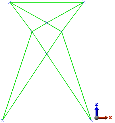
The model should display as shown in the following image.