This topic describes how to create and apply heat exchanger materials. Several application examples are presented to illustrate the three different modes of heat exchanger operation.
For modeling guidelines and results extraction, click here.
To assign a Heat Exchanger Material
- Open the Material quick edit dialog. There are several methods:
- Left click on the part, and click the Edit icon on the context toolbar.
- Right click on the part, and click Edit...
- Right click on the part name under the Materials branch of the Design Study bar, and click Edit....
- Click Edit in the Materials context panel.
- Select one or more parts.
- Select the database from the Material DB Name menu.
- Select Heat Exchanger from the Type menu.
- Select the material from the Name menu. (There are several commercially-available heat exchanger models included in the database.)
- Select the heat exchanger inlet (a) and outlet (b):
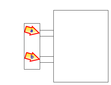
- Click Apply.
To Create and Edit a Heat Exchanger Material
- To open the Material Editor, click Material Editor on the Materials context panel.
- Click the List button.
- Right click on a custom database, and select New material. Select Heat Exchanger. Specify a Name.
- Click the property button that is to be defined.
- The two properties that define a heat exchanger are Flow and Heat Transfer. For each property, select the variation method, enter the appropriate value and units, and click Apply.
- Optionally, click Save.
- Click OK.The new material is available when the Materials quick edit dialog is opened.
Property: Flow
Specify the amount of fluid that moves through the heat exchanger device. Use either a constant value or a fan characteristic (pressure-flow curve).
Constant:
Enter the flow rate Value and appropriate units.
Fan Curve:
Specify the Flow Rate and Pressure Head values. This information is usually supplied by the manufacturer.
Property: Heat Transfer
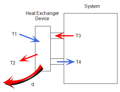
Define the thermal behavior of the heat exchanger device. The following heat exchanger device schematic illustrates the conventions used in the variation methods descriptions:
There are several property variations to simulate different physical models:
Heat Exchanger
The Heat Exchanger mode removes heat from the working fluid. Conceptually it is similar to a physical heat exchanger device.
Specify the following:
- The input Temperature, T1. In many cases, T1 is the ambient air temperature.
- The Heat Capacity of the heat exchanger device. The is the amount of heat required to change the temperature by 1 degree.
Heat Exchanger Application Example
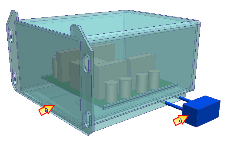
A cabinet-type heat exchanger (A) is used to extract heat from a sealed industrial automation system. The heat exchanger circulates air throughout the system, and rejects heat to the surroundings. This is useful for sealed systems exposed to harsh environments.
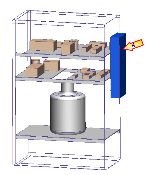
System settings:
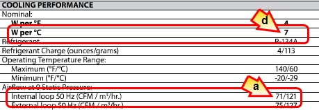
- Flow Variation method = Constant. Flow rate = 71 ft³/min.
- Heat Transfer Variation method = Heat Exchanger
- Temperature = 30 °C (the ambient temperature surrounding the system)
- Heat Capacity = 7 W/K.
The flow rate and heat capacity values were taken from manufacturer-supplied specifications for the device:
Temperature Change
The Temperature Change variation simulates a known temperature rise or drop (T3 - T4).
Temperature Change application example
A heat exchanger device (A) cools the liquid refrigerant in a cold plate (B). The cold plates controls the temperature within an electronics module. We use Temperature Change because the cold plate maintains a known temperature drop within the working fluid.
System settings:
- Flow Variation method = Constant. Flow rate = 0.1 gal/min.
- Heat Transfer Variation method = Temperature Change
- Temperature Change = -1°C (A negative value means the heat exchanger cools the working fluid.)
The value of Temperature Change came from the manufacturer-supplied thermal characteristics of the cold plate:
- The area of the cold plate surface is 18 in².
- The electronics module dissipates 15 W.
- At a flow rate of 0.1 gal/min, the thermal resistance of the specific cold plate model is approximately 1.24 °C in² / W.
- The heat exchanger device must deliver a temperature change of 1 °C to simulate the effect of the cold plate.
Heat input/Extraction rate
The Heat input/Extraction rate variation simulates the addition or removal of heat to the working fluid. It is an ideal way to simulate data center CRAC devices. The heat extraction rate is often supplied by CRAC manufacturers.Be sure to specify a temperature or film coefficient boundary condition on the system. Otherwise the thermal solution is unbounded, and may produce unrealistic temperatures. The result is solution divergence.
Heat input/Extraction rate application example
A heat exchanger device (A) simulates the effect of a CRAC (B) unit in a data center. The objective is to remove a specific amount of heat.
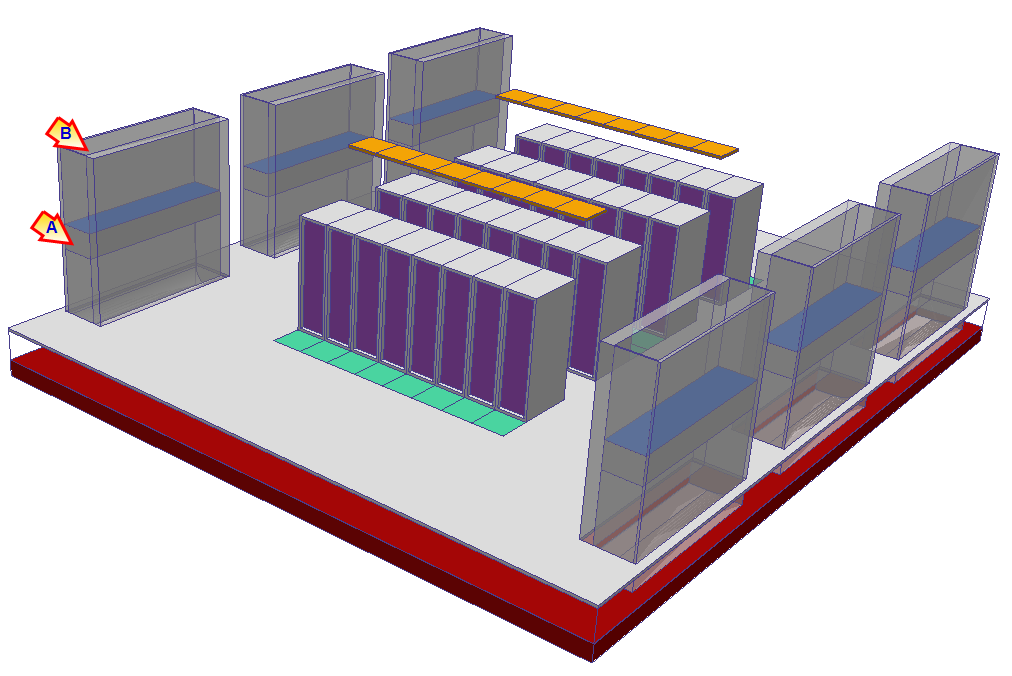
We've modeled the heat exchanger device as a rectangular block within the CRAC. Also, the CRAC unit part is suppressed (not meshed). For more about modeling CRAC units, click here.
System settings:
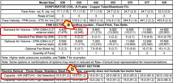
- Flow Variation method = Constant. Flow rate = 5500 ft³/min.
- Heat Transfer Variation method = Heat Input/Extraction Rate
- Heat Input/Extraction Rate = -51200 BTU/hr. (A negative value indicates that heat is removed from the working fluid.)
The flow rate and heat input/extraction rate were taken from manufacturer-supplied data:
Air Conditioner
This method simulates an air conditioner that delivers air to the environment at a prescribed temperature (the Set Point Temperature). This is T4, the air temperature leaving the heat exchanger device.
Use this method to simulate air conditioner and CRAC units that deliver air at a constant temperature. At the conclusion of the simulation, the Heat Absorbed output quantity (in the Heat Exchanger tooltip) indicates the performance of the device.