A good understanding of the thermal behavior of AEC, Data Center, and other architectural applications is essential for protecting expensive electronic components and data. Such an understanding promotes system sustainability and ensures human thermal comfort.
Heat exchangers and air conditioners are common elements in these systems, and play a significant role in their thermal management. Proper simulation of both is essential for optimizing thermal behavior.
The Heat Exchanger material device addresses this need. The Heat Exchanger device simulates several different heat exchanger devices commonly found in AEC, Data Center, and other architectural applications:
- Heater or a chiller devices in HVAC, AEC, and architectural environments
- Computer Room Air Conditioner (CRAC) units
- Computer Room Air Handler (CRAH)
- Computer Air Conditioner (CAC)
- Air to Air coolers
- Liquid Coolers
- Air Conditioners
The device represents the physics on simple geometry, thereby reducing the complexity of the model.
Modeling Guidelines
Build the heat exchanger (1) so that it is not immersed within the system (2):
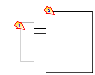
Construct a volume at the inlet (1) and outlet (2) to offset the device from the system:

The heat exchanger should not touch the system. The material of both extensions should be the system working fluid.
Construct the inlet (1) and outlet (2) with a single, separate, planar surface:
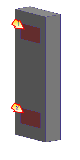
At the conclusion of the simulation, the Heat exchanger openings are listed in the Summary file as system openings:
- Heat exchanger inlets appear as a model outlets (pressure = 0).
- Heat exchanger outlets appear as a model inlets (volume flow rate).
CRAC units
When simulating data center CRAC units, it is not always feasible to build the device completely outside of the system (as shown above).
A good technique is place the heat exchanger device (1) inside of the CRAC unit (2), and suppress (don't mesh) the CRAC unit part.
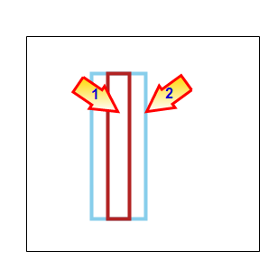
The heat exchanger device does not touch the mesh on the system (except at the inlet and outlet). This satisfies the requirement that the heat exchanger not be immersed within the system.
For an example of defining a heat exchanger device in a CRAC, click here.
Considerations and Limitations
- The Heat Exchanger material device is specifically designed to simulate closed-loop heat exchanger devices. It does not support open-loop systems (energy recovery and recapture of conditioned air).
- If your model contains multiple heat exchanger devices, assign each one individually. Do not assign a heat exchanger material to more than one part at a time.
- Do not assign any flow or thermal boundary conditions to the heat exchanger part.
- The heat exchanger material device cannot transfer more heat than allowed by specified physical constraints on the model.
- A uniform pressure condition is automatically applied at the heat exchanger inlet. For this reason, do not locate heat exchanger devices in pressurized areas. This can cause excessive flow to be drawn into the heat exchanger device.
Data Extraction and Results Visualization
A tooltip displays the resultant heat exchanger performance data. To view the tooltip, hover over the heat exchanger part (while the Global result task is active) or over the part in the Results > Material branch of the Design Study bar. The tooltip contains the following information:
- Heat absorbed: the amount of heat transferred by the heat exchanger normalized by time. This is also an indicator of how much capacity is required. For air conditioning (AC) units and CRAC units, this can be translated into energy usage.
- Temperature change: the temperature difference between the heat exchanger inlet and outlet (Tout - Tin).
- Pressure drop: the pressure difference between the heat exchanger inlet and outlet (Pout - Pin).
- Volume Flow rate: the volume of fluid that is transported through the heat exchanger device. This is usually the value specified as part of the material definition.
Note that this data is also available in the Summary file. (Results tab > Review panel > Summary File.)
The following shows that no results are displayed on the heat exchanger device (A). To view its effect on the system, display temperature near the inlet and outlet:
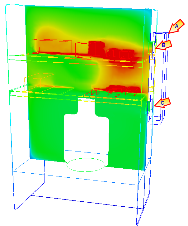
The air at the heat exchanger inlet (B) is clearly warmer than the outlet air (C). The temperature drop indicates that this heat exchanger has removed heat from the working fluid.
Related Topics