On the Job Preferences dialog, you can define parameters for a vertical section of a structure model.
Use the tabs on the dialog to define parameters:
- General parameters tab
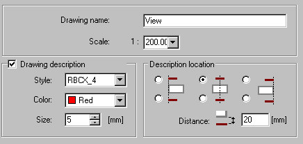
- Specify a drawing name and scale
- Drawing description - select this in order to specify Style, Color, and Size
- Description location - define the location of a description in a foundation plan drawing and a distance between the description and the view drawing.
Note: If you select Drawing description, the defined drawing name will be included in the Object Inspector dialog and in the created drawing (as a drawing title). If you clear Drawing description, the defined drawing name will be included only in the Object Inspector dialog. - Visible elements tab - define parameters for contour edges and hatching
-
As in the model / By element type / By material (available for Hatching only)
-
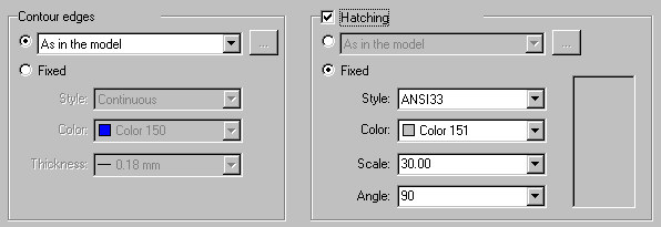
Fixed - lets you specify parameters
o Contour edges - line style, color, and thickness
o Hatching - style, color, scale, and angle
-
-
Cut elements tab - use the options on this tab (which are the same as those on the Visible elements tab) to define the display of cut elements in a vertical section.
-
Invisible elements tab - use the options on this tab (which are the same as those on the Visible elements tab) to define the display of invisible elements in a vertical section.
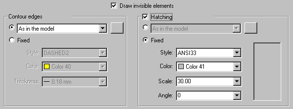
Invisible elements are displayed in the vertical section if the Draw invisible elements option is selected.
-
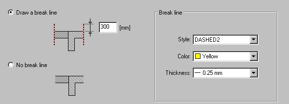
Breaks tab - use the options on this tab to define the display of breaks in the vertical section
-
Draw a break line - break lines will be displayed, and you can specify style, color, and thickness for the break line. You can also define the length of the line outside the structure model element
-
No break line - break lines will not be displayed.
-
See also: