Set preferences for the Unwrap UVW modifier editor using controls on the Unwrap Options dialog.
Interface

Colors group
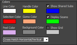
Contains color swatches to customize the display of the UVW lattice. With certain maps, the default colors may become difficult to see. Use these swatches to choose colors that work better for your specific map.
To change a color, click its swatch and use the Color Selector to choose a new one.

- Line Color
-
Specifies the color of the UVW lattice lines. Default=white.
- Handle Color
-
The color assigned to patch handles. Default=yellow.
- Show Shared Subs
-
When on, non-selected sub-objects shared by the current selection are highlighted in this color. In most cases, the shared sub-objects are edges. With a single vertex, the shared sub-objects are vertices. Defaults=on, blue.
- Selection Color
-
Specifies the color of selected UVW sub-objects. Default=red.
- Gizmo Color
-
The color assigned to the Freeform gizmo. Default=orange.
- Display Seams
-
When on, lets you assign a distinctive color to coordinate clusters' boundaries that appears in the viewports. Defaults=on, green.
- Peel Color
-
The color assigned to peeled clusters when Peel Mode is active. Default=violet.
- Background Color
-
The color assigned to the background where the texture map isn't displayed. Default=dark gray.
- Show Grid
-
When on, the grid lines are visible. Defaults=on, dark blue.
You can also set the grid size.
- [drop-down list]
-
Lets you assign a fill pattern to selected faces. Default=Cross Hatch Horizontal/Vertical.
Display Preferences group
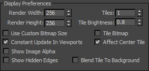
Contains controls affecting the map display in the view window.

- Render Width
-
Specifies the width resolution of the image displayed in the view window. This does not change the size of the image, but only the resolution.
- Render Height
-
Specifies the height resolution.
- Use Custom Bitmap Size
-
When on, scales the bitmap texture to the values specified by Width and Height. You can adjust these settings to scale and reproportion the bitmap texture in relation to the texture coordinates. This scaling doesn't affect the bitmap in the material, but only as viewed in the editor.
Tip: When working with large textures, reduce the bitmap size for faster feedback. And when working with disproportionate textures, setting the dimensions closer to each other in the editor can make it easier to work. - Tiles
-
The number of times the texture image is repeated, counting outward in eight directions (the four corners and the four sides).
With Tiles=1, the result is a 3 x 3 grid. With Tiles=2, the result is a 5 x 5 grid, and so on.
You can toggle the tiling feature with the Tile Bitmap checkbox, described below.
- Tile Brightness
-
Sets the luminosity of the tiled bitmap. At 1.0, the brightness equals that of the original image; at 0.5 it's half the brightness; and at 0, it's black.
Tip: Turning off Affect Center Tile (see following) prevents the Brightness setting from affecting the center tile, so it's easier to find if you've turned down the brightness. - Tile Bitmap
-
When on, you can repeat the bitmap in the editor, displaying tiling set in the material.
You can use any part of the tiled image for setting texture coordinates. This is helpful when the sections of the texture image are packed tightly together and the mesh contains many different areas to map.
- Affect Center Tile
-
When on, the Tile Brightness setting (see preceding) affects all tiles equally. When off, the center, or “home,” tile always remains at full brightness, so you can easily distinguish the home tile from the copies.
- Constant Update in Viewports
-
Affects the adjusting of UVW vertices in the viewport while you move the mouse. Default=off (the effect of adjusting the UVW vertices does not appear in the viewport until you release the mouse).
- Show Image Alpha
-
Displays the alpha channel of the background image in the editor, if it exists.
- Show Hidden Edges
-
Toggles the display of face edges. When off, only faces appear. When on, all mesh geometry appears.
- Blend Tile to Background
-
Affects the color to which tiles set to Brightness less than 1.0 blend. When off, tiles blend to black. When on, tiles blend to the background color.
Misc. Preferences group

- Center Pixel Snap
-
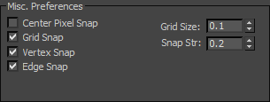
When on, snaps to the center of pixels of the background images instead of pixel edges.
- Grid Snap
-
When on, snaps to grid edges and intersections.
- Vertex Snap
-
When on, snaps to texture-coordinate vertices.
- Edge Snap
-
When on, snaps to texture-coordinate edges.
- Grid Size
-
Sets the spacing of horizontal and vertical grid lines. Default=0.1.
Setting Grid Size to 0 effectively turns off the grid. At the highest value, 1.0, the grid is the same size as the texture.
- Snap Str(ength)
-
Sets the grid snap strength. Default=0.2. Range=0 to 0.5.
Setting the strength to 0 effectively turns off snapping. At values less than 0.3, grid snapping tends to go to grid edges. At the highest value, 0.5, grid snapping goes only to grid intersections.
Selection Preferences group

- Soft Selection Edge Distance
-
When Soft Selection is on, limits the falloff region by the specified number of edges between the selection and the affected vertices. The affected region is measured in terms of "edge-distance" space rather than absolute distance. Default=16.
- Single Click Hit Size
-
Sets how far away you can click from a sub-object to select it. Default=4. Range=1 to 10.
- Selected Tick Size
-
Sets the size of the square icon the editor window uses to indicate selected vertices. Default=2. Range=1 to 10.
- OK/Cancel/Defaults
-
Click OK to accept, or Cancel to cancel the changes in the dialog. Click Defaults to restore all settings in this dialog to default values.
 Options button