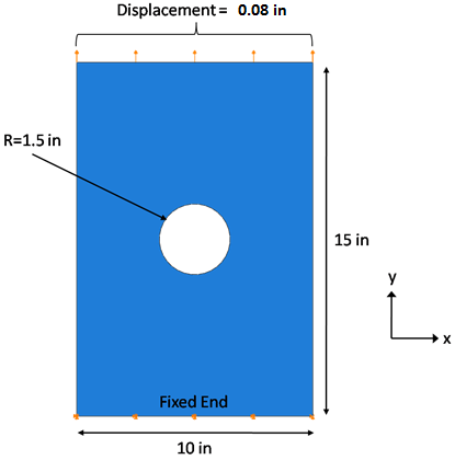
The problem consists of a flat composite plate with a hole in the center. It is subject to fixed boundary conditions on one end, and a displacement controlled load of 0.08" (0.53% of the plate length) on the other end. The plate is made of IM7/8552; the layup is [0/±45/90]s, and the ply thickness is 0.005" resulting in a plate thickness of 0.04". The seed size for the mesh is 0.2, and reduced integration continuum shell elements (SC8R) are used. The dimensions, boundary conditions, and load are shown below. After the model is created and the finite element analysis is completed, steps are provided to view and interpret the results.
In this tutorial, elementary modeling details are omitted. It is assumed you have previous experience in the Abaqus/CAE environment. Please refer to the Abaqus documentation before completing this tutorial if you are unfamiliar with Abaqus/CAE.
If you are interested only in learning how to interpret results from Simulation Composite Analysis, an Abaqus input file (ASCA_Tutorial_3_Abaqus.inp) is available for download which can be used to generate an Abaqus output (*.odb) file. In this case, run the input file and refer to the View and Interpret Results section.