The materials table allows the user to enter, edit or delete materials, gauges (thickness) and stock sheet sizes that can be assigned to fittings and parts to be manufactured.
Please use the Navigation & Toolbars topic for information on how to access the Global database using your application. Select Manufacturing  Materials option.
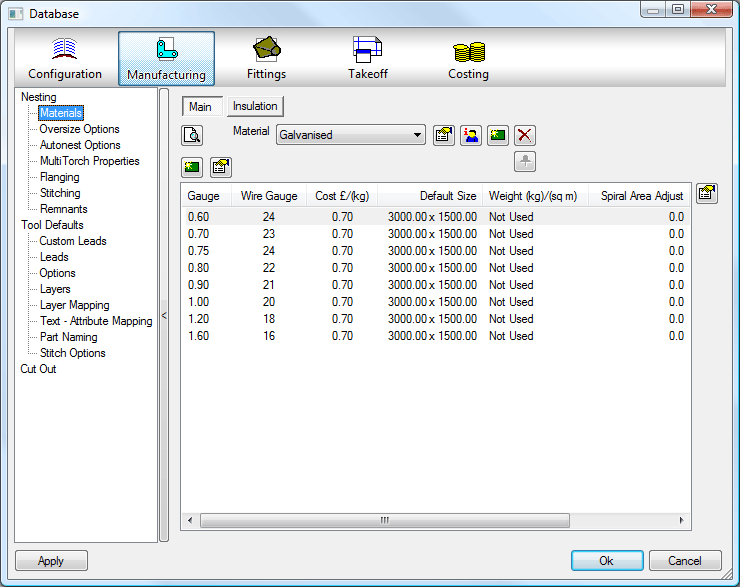
The Material Database is split into 2 Tabs, Main and Insulation. Both work the same way but allow for the separation of Manufacturing material and Insulation Materials.
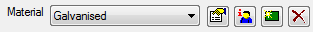
Material
Click the  icon to create a new material.
- A prompt will ask if the new material is to be based on the current displayed material. Replying Yes will often save typing in all of the thickness and sheet sizes again, the user will then be prompted to assign current Specifications to the material if applicable.
Click in the Name to change the name from "Untitled " to the name required.
Click on the  icon to delete an existing Material.
Click on the  icon to display the Material Properties Screen.
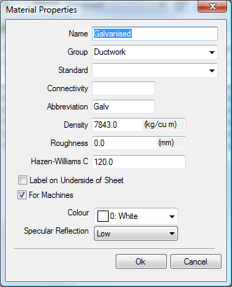
The Material Properties dialogue window allows the user to define Groups, Standards and Material information that will be used in reports, and if using Pressure in Design Line , supplies airflow information.
Group
Can be used to group materials together into groups such as ferrous and none ferrous. When data is entered it will be stored for future selection on other materials in the drop down boxes.
Standard
The Standard field allows extra information to be attached to the material which which would show the material as being of a certain grade, such as a British Standard etc. When data is entered it will be stored for future selection on other materials in the drop down boxes. This is also available as a print object.
Connectivity
A material can be assigned a connectivity tag, this is to be used in conjunction with the "Coupling" pattern in order to be able to attach different materials to one another. This is used within the connected drawing mode of quick takeoff, and more in our CAD-Package.
Abbreviation
An abbreviation for the material name can be entered here, commonly 3 or 4 characters long STLS for example generally used on reports to reduce the amount of data on a report.
Density
Is used to calculate the weight of a part from its thickness and size. In metric units the density is measured in kg/m3, whereas in imperial the units are lb/ft3.
Roughness
Value applied to a material so pressure drops can be accurately calculated on pipe work. This is also available as a print object.
Label on Underside of Sheet
Is to force the flipping of the sheet, so the developments are turned over. Useful for materials or items which will end up on show.
For Machines
When ticked this material will appear in the Installed Machines Tools window so that Lead Ins, Kerf Values etc can be applied to the Material, if unchecked then any Items assigned to this Material will not be nested.
Colour
A colour can be applied to the Material for use in Takeoff, Design Line, and CADmep+ Drawings. If Use Material Colour is used in Takeoff the Items made with this material will carry that colour.
Specular Reflection
Specular reflection is the mirror-like reflection of light (or of other kinds of wave) from a surface, in which light from a single incoming direction (a ray) is reflected into a single outgoing direction. This can be emulated using OpenGL and applied to the Material
Click OK to return to the Database Editor.
 Owner Information is used by Autodesk to assign materials to Product Listed and Content Driven Items.
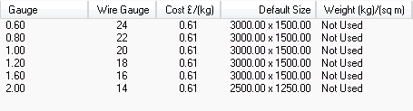
All of the gauges (sheet thickness) currently assigned to the active material are displayed here. Gauges are sorted into thickness order. Use the scroll bar if necessary to display all of the values. Right Click on the gauge line and select Delete to delete a gauge from the material.
Click on the icon at the top of the gauge column to add a new Gauge or double click on an existing line to amend the data.
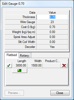
Each gauge can have one or several sheet sizes (Length, Width and Product Code) assigned. Sheet sizes determine at which point the oversize check is applied. Clicking the  will delete that sheet size. For multiple sheet sizes at the same gauge, the sheet size to be used as the default by automatic nesting should be assigned the
  . Product Codescan be applied to the materials for use in reporting and Costing. Sheet sizes are also split into Flatbed sheets and Rotary which was introduced for Rotary Nesting.
Wire Gauge
Standard Wire Gauge (SWG) is a method of defining sheet thickness that is often used by the ductwork and sheet metal industries who work with thin plate. The wire gauge can be displayed instead of thickness on various screens and printouts.
Approximate Wire Gauge - inches - mm
| SWG | Inches | mm |
| 01 | 0.300 | 7.620 |
| 10 | 0.128 | 3.251 |
| 12 | 0.104 | 2.642 |
| 14 | 0.080 | 2.032 |
| 16 | 0.064 | 1.626 |
| 18 | 0.048 | 1.219 |
| 20 | 0.036 | 0.914 |
| 22 | 0.028 | 0.711 |
| 24 | 0.022 | 0.559 |
| 26 | 0.018 | 0.457 |
The icon is used to create Material Specific diameter adjustment sets.
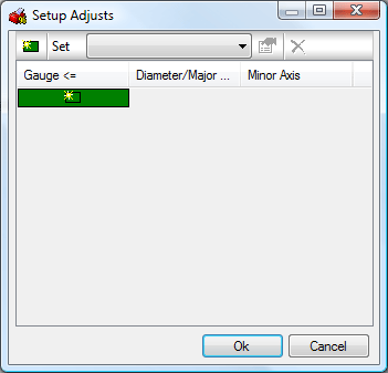
These are then applied to the Connector when Material Specific is selected in the Round Connector Database. For more details please browse to theConnectors section of this help.
The green icon will prompt you to give the new set a name, you can then specify a gauge that the adjustments will apply to.
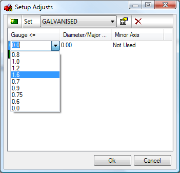
An adjustment can then be made to the Diameter/Major Axis and the Minor Axis when this Set and Gauge are applied to the connector in the Round Connector Database.
Multiple sets can be created to allow different adjustments to be applied.