The tools associated with a machine can be customised to take account of specific requirements of individual controllers. To access the dialogue Click on File > Setup > Installed Machines or select the Installed Machines icon from the Utility Bar. The Installed Machines dialogue box will be displayed.
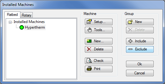
Normally, only one machine controller will be shown, and it will be highlighted in blue with a green dot alongside to indicate that it is the default machine. In cases where there are multiple controllers, only one of them will have the green default setting. Click Tools. The Edit Tools for Machine dialogue box will be displayed.
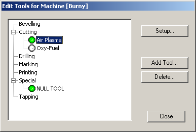
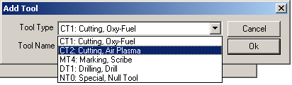
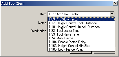
Highlight a tool e.g. Air Plasma in this instance, and click Setup. If there are no tools assigned, click on Add Tool and choose a relevant tool from the drop-down list, as shown below.
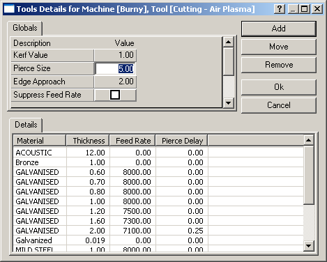
After clicking on Setup for the tool, the Tool details for Machine dialogue box will be displayed.
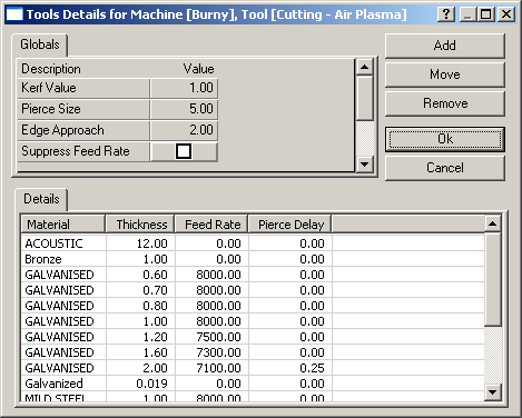
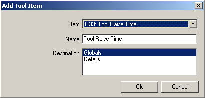
This screen details the specific tool settings for all combinations of material and gauge that exist on your database. Some of the settings apply globally (e.g. Pierce Size) whereas others differ with each material and gauge (e.g. Feed Rate), details of the most common options can be found http://beehive.autodesk.com/community/service/rest/cloudhelp/resource/cloudhelpchannel/guidcrossbook/jsonp?v=2015&p=FABRICATION&l=ENU&guid=GUID-BEADE391-1DA7-4304-BF81-4FFF998DFA06. More parameters can be added to the list if required for the controller and tool, by clicking the Add button and clicking the down arrow to see a list of valid parameters:
Then, for the chosen parameter, you have the option to apply it globally or at a detailed material / gauge level
To edit any of the global parameters, click in the field and change the value:
Pierce Size
This refers to a hole diameter. The cutting machine will pierce any hole that has a diameter less than or equal to the entered value.
Arc Slow Min
The % value is the minimum percentage that the machine will slow to when it comes to a radius less than or equal to the value in the Arc Slow Radius field. The machine will not drop to this minimum percentage speed instantly, and the drop is proportional to the size of the element.
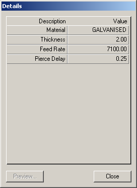
To alter any of the material detail entries, double-click anywhere on the row that you wish to change. The Details dialogue box will be displayed:
Feed Rate
This value is in mm per minute for this material and gauge. On some controllers, the feed rate is defined within the controller and this value is treated as information only. If the Suppress Feed Rate option is chosen, either globally or at this detail level, the feed rates will not be written away to the NC data.
Pierce Delay
This is the time in seconds that it will take for the cutting tool to pierce a hole at this combination of material and gauge - i.e. the time that the torch will be stationary while the hole is cut.
Kerf Value
This caters for the thickness of the cutting tool. The value entered here is the width of material that will be removed by the cutting tool (from the Old English coerf - groove). Kerfing will be defined for the tool as to the left or the right, and works in conjunction with the cut side - refer to Tool Use for more information.