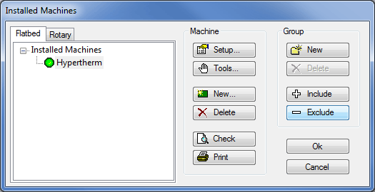
The Installed Machines dialogue is where you set up the machines that will write NC data for the jobs created in our software. To access and amend this dialogue Click on File > Setup > Installed Machines or select the Installed Machines icon from the Utility Bar.
- To amend an existing machine click on the
 button or double click the name of the machine.
 -
To setup and amend the Tools fitted to the machine click the
 button.
 -
To install a new machine click on the
 button.
 -
To delete an installed Machine, click on the machine name, as in the picture above, and click the
 button.
 -
The
 button is used to check the material / tool settings of the machine, and will display a dialogue box of any settings that have not yet been configured , as shown below.
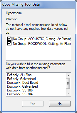
- The
 button will print out a complete list of settings configured within the 6 tabs of the Machine Editor Dialogue and the Installed Machines dialogue.
Amending an existing machine or creating a new machine will bring up the Machine Editor dialogue box as shown below. There are 6 sections in this dialogue, each of which are attainable through their own tab and will be covered in their own section elsewhere within this help.
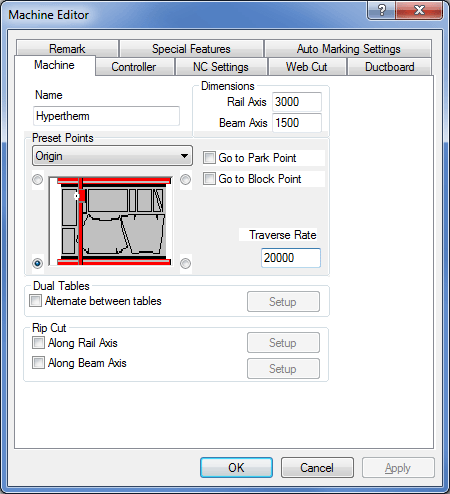
Name
The name of the machine can be changed here. Each machine will have a folder assigned to it. The folder contains various files applicable to that machine and the tools it uses. The folder name is the same as the machine name and exists in the database folder in the installation directory. For example The machine name "Burny" settings will be placed in the "C:\CAM\DATABASE\Burny" folder. If the machine name is changed, the folder name is also changed.
Dimensions
Units are in mm or inches.
Rail Axis
The maximum length over which the tools can operate along the long machine axis.
Beam Axis
The maximum length over which the tools can operate along the short machine axis.
Preset Points
The diagram of the Machine has a button in each corner. These are used to determine four key reference points. Reference points rotate the X and Y axis; they are never reversed.
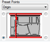
Select a reference point and then click on the required corner.
Origin
Set to define the machine's x/y axis orientation and, in most cases the x=0, y=0 point. This is machine/controller dependent and after installation should not be altered unless instructed by the software vendor. If the 0, 0 point does not coincide with this convention, choose the axis convention here and then enter a machine zero offset in the controller section.
Home Point
The position where the machine will return to when home is selected on the controller.
Start Point
The machine will start to cut a nest from this point. If this is not the same as the home point, the tool will make a rapid traverse to the corner of the nest determined by the start point.
Park Point
The position the tool will return to after the parts are cut, provided that the ' Go to Park Point' tick box is ticked.
Block Point
The Block Point is used in Level 1 Installations where NC is written for a single part in Profiler. The Block Point is a single point on the bounding rectangle of the part, the last line of NC would be a command to move back to the Block Point so the same part could be cut again. If " Go to Block Point" is ticked then the tool will return here after cutting has finished.
Nesting
Allows the user to specify a Nesting position on the plate different from the Home position.
Traverse Rate
Enter the speed at which the tool head will move when in rapid traverse - typically 20,000 mm/minute or 800"/minute, but check with your machine supplier. This value is used to accurately calculate the time to cut a sheet of parts.

Dual Tables
Some machines can have two cutting tables or are long enough to allow two sheets to be mounted along the length. The software can be set up to move between tables automatically.
Alternate between Tables
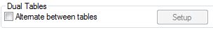
Tick if you wish to automatically move between both table home positions. ClickSetup to display:
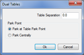
Table Separation
Sets the sheet home point separation distance.
Park Point Specifies whether the cutting head is parked at the local machine park point or midway between the dual tables.
Rip Cut
Before or after cutting a nest, the program can rip cut any remaining length or width of the sheet dependent on the settings here. A rip cut is a latitudinal or longitudinal cut that separates unused sheet from the part of the sheet that has been cut upon.
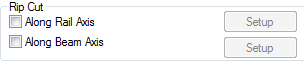
If the rip cut is selected there are different ways it can be implemented.
Along Rail Axis
Cuts the sheet along the rail length.
Along Beam Axis
Cuts the sheet along the beam axis.
To specify the type of cut (rail or beam) and the various options, once the appropriate rip cut box is ticked click on Setup. This opens up a new window which enables the following options.
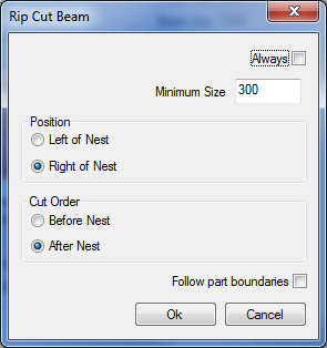
Always
With this option ticked the machine will always perform the rip cut as specified.
Minimum Size
The rip cut will only be performed if the remaining sheet is going to be at least the Value specified in this box.
Position
Allows the rip cut to be set either above nest or below nest in the case of a Rail Cut and Left or Right of Nest on a Beam Cut.
Cut Order
Allows the rip cut to be performed either before or after the rest of the nest has been cut.
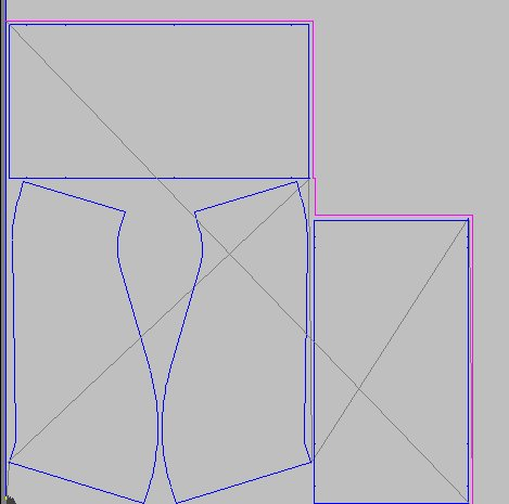
Follow part boundaries
Sets the rip cut to follow the outside of the parts on the nest allowing for the margin between nested parts. The screen-shot below shows how the rip cut follows the part boundaries along the rail axis.
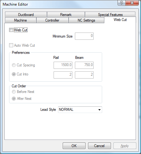
The Web Cut tab is used to define the criteria for web cutting the material that remains on the sheet after the profiled parts have been cut out, on order to make the scrap more manageable. It is usually used with oxyfuel cutters as opposed to plasma cutters.