Next, run a contouring toolpath along the outside of the part.
- On the ribbon, click CAM tab
 2D Milling panel 2D Contour
 .
.
 Tool tab
- On the Tool tab, click
 . Remember: Tool definitions can be saved in a library or just for the part you work on. In this example, we will save the tools in the part only. You can always copy the tools to a library at a later time, if you wish to re-use them.
 - Click
 .
. - Click the Cutter tab.
- Change Flute length to: 25 mm
- Click the OK button to create your new tool.
- Click the Select button to select the tool for your operation and close the Tool Library dialog.
Add a new tool with modified dimensions.
You can use the default tool type and dimensions (an Ø8 mm flat mill) for this tutorial, but increase the flute length to be able to cut the entire height of the part (22 mm).
Feed & Speed Group
Expand the Feed & Speed group and change the following parameters:
- Spindle speed to: 3000 rpm
- Cutting feedrate to: 800 mm/min
 Geometry tab
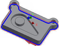
- Click the Geometry tab. Ensure that the Contour selections button is active so that you can select the outside edge of the part geometry to run the tool around.
- Move the mouse over the bottom front edge. When it highlights, click on it. The bottom contour of the part is chain selected automatically.
- An arrow then appears near the chained contour indicating the direction of the toolpath. You can reverse the direction of a selected edge by simply clicking the arrow.
- Do not close the Operation dialog box if you are satisfied with your selection, as that will end the 2D Contour operation. Instead, simply proceed to the next step of this tutorial.
 Heights tab
- Click the Heights tab. A preview of the heights is shown.
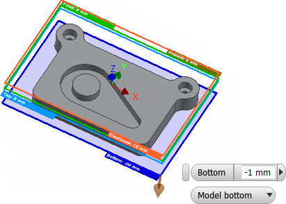
- From the Bottom Height drop-down menu, select Model bottom.
- Change Bottom offset to: -1.0 mm
Preview of heights: The top orange plane represents the Clearance Height. The second olive green plane represents the Retract Height. The green plane represents the Feed Height. The light blue plane is the Top Height. The dark blue plane is the Bottom Height.
To make sure that the tool gets all the way through the stock, lower the bottom height by 1 mm.
Observe that the preview plane moves in the graphics window.
Start the Calculation
- Click
 at the bottom of the Operation dialog box, or right-click in the graphics window and select OK from the marking menu, to automatically start calculating the toolpath.
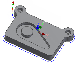
The toolpath is calculated and shown in the graphics window.
Continue to To Machine the Pocket...