Display > UI Elements > Channel Box/Layer Editor

The Channel Box is the primary, fastest, and most streamlined tool for editing object attributes. It lets you quickly set keys, and lock, unlock, or create expressions on attributes.

Like the Attribute Editor, you use the Channel Box to modify an object’s attribute values. The Channel Box is different from the Attribute Editor in the following ways:
- It displays only the keyable and nonkeyable displayed attributes for the selected object. This lets you easily access nonkeyable channels from the Channel Box without running the risk of accidentally keying them. You can make a channel keyable or nonkeyable from the Channel Box.
You can also make a channel keyable, nonkeyable displayed, or nonkeyable hidden from the Channel Control Editor. See Channel Control Editor.
- It takes up much less space in the window.
- You can control construction history.
The information displayed in the Channel Box varies, depending on what kind of object or component you have selected. If you haven’t selected an object, the Channel Box is blank.
The Channel Box will sometimes incorrectly display an enumerated attribute's pull-down menu. Extra menu items can appear that represent the numbers in between non-sequential option values. To fix the problem, specify sequential values for the options of any enumerated attributes that will appear in the Channel Box. For example: “solo=1:triplet=2:quintet=3”.
Attributes
When you select a geometric object, the Channel Box displays these sections:
| Section | Usage |
|---|---|
| objectName | Lists the keyable transform attributes that translate, scale, and rotate the object’s absolute position in the world space. Also shows the object’s visibility attribute. |
| SHAPES | Lists the names of nodes that define the geometry of the object. Other nodes, such as related particle emitters may be found here. |
| INPUTS | Lists the names of other nodes that affect this one. Typically, these comprise the “construction history” of the node. |
| OUTPUTS | Lists the names of the output nodes (nodes that receive data) for this node. |
If you’ve selected two or more objects, the Channel Box displays the attributes for the last object selected only. To display the attributes in the Channel Box of another selected object, select Object > objectName.
Edits you make in the Channel Box affect all selected objects of the same type as the one displayed.
Component attributes
If you display attributes of an object component, the Channel Box displays only one section for shape attributes that pertain to the component.
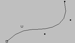
For example, suppose you’ve created a NURBS curve with the following CVs:

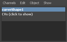
If you turn on component selection mode (in the main menu bar) and select the CVs, the Channel Box displays this:

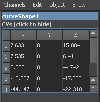
You can display the CV values in the Channel Box and enter new values. To display the values, click CVs (click to show) in the Channel Box.

Channel Box colors
The following colors represent the state of channels in the Channel Box:

| Locked | Gray |
| Nonkeyable | Light Gray |
| Muted | Brown |
| Blended | Green |
| Keyed On Frame | Red |
| Keyed Off Frame | Dark Pink |
| Key Altered | Light Pink |
| Expression | Purple |
| Constrained | Blue |
| Connected | Yellow |
INPUTS
Use the INPUTS component of the Channel Box to modify an object’s construction history.
Related topics
- Nodes and attributes overview
- Change attribute values in the Attribute Editor or Channel Box
- Show or hide the manipulator for an attribute in the Channel Box
- Lock the value of an attribute
- To make a channel keyable or nonkeyable
- Create, edit, or delete custom attributes
- Control the display of attributes in the Channel Box
- Display the Channel Box
- Organize the Channel Box
- Work with the Channel Box
- Channel Box menus