In this task, you will design a simple cooling circuit layout using the Cooling System Wizard.
The Wizard cannot create all the possible features of a cooling system, but it is excellent for creating a quick initial layout that can serve as the basis for a more complex cooling system, for example, including bubblers, baffles, and other cooling aids.
- Ensure the Modeling tutorial project you created in task 1 is open.
- Click
 .
. - Select the Files of type drop-down list. The list of file types directly supported is shown. Select Study files (*.sdy) .
- Navigate to the tutorial folder, typically C:\Users\Public\Public Documents\Autodesk\Simulation Moldflow Synergy 20xx\tutorial.
- Click the file model_4_cooling.sdy and click Open.
Note: The Cooling Circuit Wizard requires the part to lie in the XY plane.
- Use the ViewCube to select the
 Front view. The model is oriented so that the parting plane lies in the YZ plane (shown in the following image). This is not the correct orientation for the successful creation of a cooling circuit.
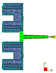
If the Cooling Circuit Wizard is used with the model orientation shown in the above illustration, the cooling circuit will be created in the XY plane. The incorrect cooling circuit that would be created is shown in the following image.
- Click
 . All elements in the model will turn pink.
 - Click
 and select
  Rotate from the drop-down menu. The Rotate dialog opens in the Tools tab.
 - Select Y Axis from the drop-down list and enter -90 in the Angle box.
- Click Apply.
- Select
 to view the layout. The XY plane is now parallel with the top surface of the model.
 - Click Close on the Tools tab in the Project pane.
- Click
 . The first page of the Cooling Circuit Wizard appears. This is used to specify the layout of the cooling circuits, in particular the channel diameters, the distance from the part surface to the cooling circuits, and the alignment of the circuits relative to the part.
 - Enter the following values on the first page of the Cooling Circuit Wizard:
- Channel diameter: 6 mm
- How far above and below: 15 mm
- Ensure that the Y alignment option is selected.
- Click Next to move on to the next Wizard page. The second page of the Wizard is used to specify the number of channels, and their spacing relative to one another and the part.
- Enter the following values:
- Number of channels: 4
- Distance between channel centers: 40
- Distance to extend beyond part: 20.
- Click Preview. The bottom of the Wizard has two additional options:
- Delete existing circuits first
- This option is active by default, and will remove any existing cooling circuits from the model before creating the circuits.
- Connect channels with hoses
- Allows the Wizard to apply the optional Hose attribute to the connecting end segments of the cooling channel; for this exercise, leave the check box deselected. Cooling circuit segments with the Hose attribute will have a heat transfer effectiveness of zero and so they do not contribute to the cooling of the part.
- Click Finish.
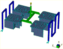
- Rotate the model to inspect the cooling system visually. Your model should now look as shown in the following image.
Tip: If you did not obtain the required results, click Undo on the Quick Access toolbar, to remove the cooling system, then click to restart the Wizard. The Wizard remembers all the settings you last used so simply step through the Wizard pages and make adjustments as required.
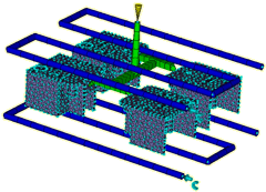
 It appears that the distance between cooling channels might be too large.
- Alter the distance between cooling channels to
30mm
using the above instructions.
You will now inspect the coolant inlet parameters automatically applied by the Wizard and change the coolant inlet temperature in both circuits to 30°C.
- Click
 , then click one of the light blue coolant inlet symbols to select it. They are situated at the start of the cooling circuits.
 - Right-click and select Properties . You will see the coolant is water and a default coolant temperature has been applied.
- Change the coolant inlet temperature to 30°C , enter Water - 30 degrees in the Name box, and click OK.
- Repeat with the other coolant inlet symbol.
It is also possible to create some or all of the cooling circuits manually. You can also change the diameter of the cooling circuits after you have created them using the Cooling Circuit Wizard. To do so, click Select, click the cooling circuit segment you want to change, right-click and select
Properties
.
Each item in the Study Tasks pane now has a  checkmark next to it, and the Analyze in Cloud step should be active. This indicates that all the preliminary steps required for your analysis have been completed. The mold is now ready to analyze. If you double-click the
  Analyze in Cloud icon in the Study Tasks pane, the analysis would start. This takes in excess of 10 minutes depending on your computer. The analysis has been done for you and will be discussed in the next task.
Click the Next topic link below to move on to the next task of the tutorial.