In this task, you will use the Runner System Wizard to design a runner system for the four-cavity layout you created in the previous task.
- Ensure the Modeling tutorial project you created in task 1 is open.
- Click
 ().
(). - Select the Files of type drop-down list. The list of file types directly supported is shown. Select Study files (*.sdy) .
- Navigate to the tutorial folder, typically C:\Users\Public\Public Documents\Autodesk\Simulation Moldflow Insight 360 20xx\tutorial.
- Click the file model_4_multi-cavity.sdy and click Open.
- Click
 () to open the Geometry tab.
 - Click
 (). The Runner System Wizard dialog appears.
 The first page of the Wizard is used to specify the runner system layout. You will identify the sprue position and the parting plane location. You also will specify whether you want to use a hot runner system.
- The Center of Mold and Center of Gates buttons specify where you would like the sprue to be relative to either the gates or the mold configuration.
Click each of these buttons to see the calculated X and Y coordinates displayed. These options produce identical results for the layout in this example. This is because you selected Offset cavities to align gates in the previous task.
- You will not create a hot runner system in this example, so leave the hot runner system creation option de-selected.
- Different parting plane configurations will affect the Z coordinate for the runner system. Click the three parting plane specification buttons Top, Bottom, and Gate Plane, and note the resulting Z coordinate. In this example, the appropriate option to select is Top, so click this option.
- Click Next to move on to the next Wizard page. The second page of the Wizard is used to specify the sprue, runner, and drop sizes.
- Enter the following values on the second page of the Runner System Wizard:
Sprue settings:
- Orifice diameter: 5 mm
- Included angle: 3°
- Length: 50 mm
Runners settings:
- Diameter: 6 mm
- Select the Trapezoidal option
- Included angle: 15°
The Drops section of the Wizard is grayed out in this example because you are not creating a hot runner system.
- Click Next to move on to the final Wizard page. The third page of the Wizard is used to specify the side and top gates to be created.
- Enter the following values on the third page of the Runner System Wizard:
Side Gates settings:
- Orifice diameter: 3 mm
- Included angle: 15°
- Select the Angle option and specify 45°
The Top Gates section of the Wizard is grayed out in this example because the injection locations are on the side of the part.
- Click Finish to create the runner system.
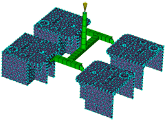
- Rotate the model to inspect the runner system visually. You should have obtained a runner system as shown in the following image.
Tip: If you did not obtain the required results or you want to modify the design, click Undo from the Quick Access toolbar to remove the runner system. Then click () to open the Wizard again. The Runner System Wizard remembers all the settings you last used so simply step through the wizard pages and make adjustments as required.
It is also possible to create some or all the runner system manually. You can also change the size and style of runners, gates, and the sprue after you have created them. To do so, click  (), click the runner segment you want to change, right-click and select Properties.
In the next task, you will use the Cooling Circuit Wizard to create a simple cooling circuit layout for the multi-cavity tool.
Click the Next topic link below to move on to the next task of the tutorial.