In this task, you will use the Cavity Duplication Wizard to duplicate the part to produce a four-cavity layout.
- Ensure the Modeling tutorial project you created in task 1 is open.
- Click
 ().
(). - Select the Files of type drop-down list. The list of file types that are directly supported is shown. Select Study files (*.sdy) .
- Navigate to the tutorial folder, typically C:\Users\Public\Public Documents\Autodesk\Simulation Moldflow Insight 360 20xx\tutorial.
- Click the file model_4_material.sdy, and click Open. As this model was used in the previous task, the study has been automatically re-named model_4_material_1 in the Project View pane.
- Rotate the model to -100 130 -25. Enter the values in the Rotation Angle text box
 () and press Enter on your keyboard. You must identify the required injection location for the Cavity Duplication Wizard to proceed.
 - From the Study Tasks pane, double-click Set Injection Locations. We will use the same injection location that was used in the previous task.
- Click the node as illustrated.
- Right-click in the Model pane and select Finish Set Injection Locations .
- Click
 () to open the Geometry tab.
 - Click
 ().
(). - Enter the following values:
- Number of cavities: 4
- Rows: 2
Ensure the Offset cavities to align gates option is selected.
- Click Preview to view the layout that will be created. The setting
Rows=2
orients the cavities such that an undesirably complex runner system would be required, as shown in the following image:
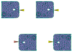
We will alter the setting to arrive at a more favorable configuration.
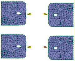
- Enter the following values in the Cavity Duplication Wizard dialog:
- Columns: 2
- Column spacing: 100 mm
- Row spacing: 70 mm
Tip: The Offset cavities to align gates option is useful when the gate is not positioned exactly midway along the side of the part. - Click Preview to view the layout.
Aligning the gates vertically in columns orients the cavities such that a much simpler runner system is required for this example.
- Click Finish.
- Using the
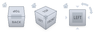 ViewCube, click Front View.
 - Click
 () to view the multi-cavity layout that has been created.
Note how the Offset cavities to align gates option has vertically adjusted the positioning of the parts.
In the next task, you will use the Runner System Wizard to create a runner system for your multi-cavity layout.
Click the Next topic link below to move on to the next task of the tutorial.