What are 2D Elements?
Thermal 2D elements are 3- or 4-node elements made from straight line segments drawn in the YZ plane. There is no heat flow (and thus no temperature change) in the out of plane direction. Only one degree-of-freedom is defined for these elements, the temperature. Temperature-dependent node material properties can be defined.
Select Types of 2D Elements
There are two types of 2D elements available for a thermal analysis. These can be selected in the Geometry Type drop-down box in the General tab of the Element Definition dialog.
- Planar: Select this option to indicate that your model is planar in nature. You must construct the model in the YZ plane.
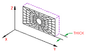
Figure 1: 2D Planar Elements
- Axisymmetric: This type of geometry must have axial symmetry in both geometry and loading. You must construct the model in the YZ plane, have the Z-axis as the axis of symmetry, and be in positive Y space. This geometry is based on the assumption that thickness-dependent quantities are expressed per radian.

Figure 2: 2D Axisymmetric Elements
Note: When using 2D axisymmetric elements, the input is based on one radian, as shown in Figure 2. The calculated heat rate of face will be based on the full circumference.
2D Element Parameters
When using 2D elements, if you are using the planar geometry type, you must define the thickness of the part in the Thickness field of the Element Definition dialog. This input only affects the total heat flow through an element face. This is calculated as the product of the heat flux (energy/area), element length and the thickness. It does not affect the temperature distribution nor the calculated heat flux.
If the geometry is axisymmetric, then this field is not available. The value 1 rad appears to remind you that an axisymmetric analysis considers a 1 radian slice. This only affects the heat flow through an element face since the area of the face becomes a function of the radial position.
Next you must specify the material model for this part in the Material Model drop-down box. The options available are as follows:
- Isotropic: If the material properties in all directions are identical, select the Isotropic option. These properties are also independent of temperature.
- Isotropic, phase change: If the analysis type is Transient Heat Transfer, then the option Isotropic, phase change will be available. Use this material model when the part may change phase from solid to liquid (melting) or from liquid to solid (freezing). The material properties are independent of temperature.
- Isotropic, phase change, temperature dependent: If the analysis type is Transient Heat Transfer, then the option Isotropic, phase change, temperature dependent will be available. Use this material model when the part may change phase from solid to liquid (melting) or from liquid to solid (freezing). The material properties in the solid phase and liquid phase are temperature dependent.
- Orthotropic: If the material properties vary along three orthogonal axes but not with temperature, select the Orthotropic option. If the Orthotropic option is selected, you will be able to orient the material axes using the Principal Axes Transformation Angle field. The local n material axis will be measured this angle counterclockwise from the Y axis as shown in Figure 1.
- Temperature Dependent Isotropic: If the material properties are identical in all directions but change with temperature, select the Temperature Dependent Isotropic option.
- Temperature Dependent Orthotropic: If the material properties vary along three orthogonal axes and change with temperature, select the Temperature Dependent Orthotropic option. You will be able to orient the material axes using the Principal Axes Transformation Angle field. The local n material axis will be measured this angle counterclockwise from the Y axis as shown in Figure 1. Tip:
- Material properties, as is required with all material models. See the page Setting Up and Performing the Analysis: Thermal: Material Properties: Isotropic Phase Change Material Properties.
- Initial temperatures. In addition to the normal requirement of setting the initial temperature for a transient heat transfer analysis, the initial state of the part with phase change solid, liquid, or some fraction in between is based on the initial temperature. Either apply initial temperatures to the part (see the page Setting Up and Performing the Analysis: Thermal: Loads and Constraints: Temperature) or assign a default global temperature (see the page Setting Up and Performing the Analysis: Thermal: Analysis Parameters: Transient Heat Transfer).
- Set the relationship used to determine the liquid fraction (see the paragraph Calculating the Liquid Fraction on the page Setting Up and Performing the Analysis: Thermal: Analysis Parameters: Transient Heat Transfer).
- An iterative process is used during the solution when a phase change material is included. The convergence tolerances may need to be smaller than you are accustomed to. See the paragraph Controlling the Nonlinear Iterations on the page Setting Up and Performing the Analysis: Thermal: Analysis Parameters: Transient Heat Transfer.
In addition to setting the material model to include the effects of phase change, the following items need to be set:
Note: Although a change in phase can be included in the transient heat transfer analysis, the motion of the fluid is not considered. For example, an ice cube will melt and change to water, but the water remains in the same location. There is no transport of heat due to buoyancy effects or motion of the fluid (for example, run-off) in a transient heat transfer analysis.
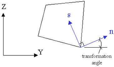
Figure 1: Principal Axes Transformation Angle
Next, you must specify how the heat flow is calculated in the Heat Flow Calculation drop-down box. If the Projected at Centroid option is selected, the heat flux for this part will be calculated from the derived nodal temperatures using Fourier's law. If the Nonlinear Based on BC option is selected, the heat flux for exterior surfaces with convection or radiation loads on this part will be calculated using the input parameters of the convection or radiation boundary condition and the derived nodal temperatures. The heat flux for interior faces is not affected by this option. If the Linear Based on BC option is selected, the heat flux for exterior surfaces with convection or radiation loads on this part will be calculated using the same method as the Nonlinear Based on BC option except that the heat flux on surfaces with radiation loads will be linearized.
It is only necessary to use the Nonlinear Based on BC or Linear Based on BC options if the actual heat flux output for the radiation or convection boundary condition is desired. The actual heat flows are based on the surface fluxes. For an adequately refined finite element mesh, the heat fluxes at the surface should be equal for all selections.
If you want two or more other parts in this model to exchange heat through body-to-body radiation through this part, select the Transparent option in the Body-to-Body Radiation drop-down box.
To Use 2D Elements
- Be sure that a units system is defined.
- Be sure that the model is using a thermal analysis type.
- Be sure that the elements that you are going to assign as 2D elements are drawn in the YZ plane. Tip: Useful commands for converting 3D models to 2D models are Draw
 Pattern Relocate & Scale, Draw Pattern Rotate or Copy, and Draw Modify Project to Plane. For example, you may accidentally create a mesh in the XY plane. You can rotate the mesh to the YZ plane using either the Relocate & Scale or Rotate command. Due to round-off, some nodes may have a small X coordinate value that prevents the element type from being set to 2D. In this case, use Project to Plane to snap the nodes exactly to the YZ plane.
 - Right-click the Element Type heading for the part that you want to be 2D elements.
- Select the 2D command.
- Right-click the Element Definition heading.
- Select the Edit Element Definition command.
- Select the appropriate geometry type for the part in the Geometry Type drop-down box.
- Select the appropriate material model for the part in the Material Model drop-down box.
- If you selected the Planar option in the Geometry Type drop-down box, specify the thickness of the part in the Thickness field.
- If you selected the Orthotropic option in the Material Model drop-down box and the principal axes do not lie on the global XYZ axes, specify the rotation angle value in the Principal Axes Transformation Angle field. This angle is measured counterclockwise from the global Y axis to the material axis in degrees.
- Press the OK button.