Use this macro to define a model of compound-profile bars. Compound bars are created as a set of objects (such as profiles, plates, and welds) that are available in the Autodesk AutoCAD Structural Detailing - Steel program.
To begin defining a compound profile, open the Compound profiles dialog from:
- Menu: Steel > Compound profiles
- Ribbon: ASD - Model > Elements > Compound profiles
- Toolbar: General > Compound profiles

- Command line: RBCT_MMACRO.
In the drawing area, click to specify the start point and the end point of the compound profile.
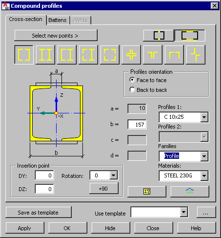
The Compound profiles dialog has 3 tabs: Cross-section, Battens, and Welds. Use the options on the Cross-section tab to define parameters of the cross-section of a compound bar, and the options on the 2 remaining tabs to define parameters of connection between chords of the compound profile. On the Battens tab, you can define battens data such as distribution along the length, size, and so on. On the Welds tab, you can define data related to thickness of welds along the length of the compound bar.
Use the buttons at the top of the dialog:
- Select new points - clicking this lets you redefine the start and the end points of a new compound profile
- connect chords of the compound profile by means of welds along the profile length. After you click this, the Welds tab becomes accessible (the Battens tab is inaccessible). Because chords of the compound profile touch each other, the edit fields for definition of spacing of chords in the compound profile are not accessible.
- connect chords of the compound profile by means of battens. After you click this, the Battens tab becomes accessible (the Welds tab is inaccessible).
Available types of the cross-section of the defined compound bar:
![]() Two C-sections set back to back or face to face
Two C-sections set back to back or face to face
![]() Two I-sections
Two I-sections
![]() C-section and I-section set back to back or face to face
C-section and I-section set back to back or face to face
![]() I-section and two angles
I-section and two angles
![]() Four angles set face to face
Four angles set face to face
![]() Four angles set back to back
Four angles set back to back
![]() Two angles with shorter or longer legs set back to back
Two angles with shorter or longer legs set back to back
![]() Two angles with shorter or longer legs set face to face
Two angles with shorter or longer legs set face to face
![]() Two angles set in the form of a cross
Two angles set in the form of a cross
In the right part of the dialog, define the following parameters:
- Type of the profile of a single chord of the compound profile (for example, C10x15.3, W 30x211). If the profile has a C-section and an I-section as well as an I-section and 2 angles, it is necessary to determine 2 profile types.
- Profile family
- Materials
Profiles available on the selection list of profile types are those defined in the Profile List dialog. To add a profile to the list, click ![]() . The Profile list dialog displays, where you can select a profile.
. The Profile list dialog displays, where you can select a profile.
Profile families available on the selection list are those defined in the Family Manager dialog. To add a family to the list, click ![]() . The Family manager dialog displays, where you can select a family.
. The Family manager dialog displays, where you can select a family.
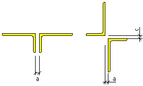
For a complete definition of the cross-section of the compound bar, it is necessary to define values of spacing between profile chords. Depending on the selected profile type, this may be 1 value and, in some cases, 2 values of the chord spacing. The drawing below illustrates a compound profile, the chords of which are 2 angles (for the profile presented on the left, a single parameter a is defined, and for the other profile, 2 parameters a and c are specified).
Under Insertion point, you can enter values for DY and DZ that let you shift the whole cross-section in the directions of the axes of the coordinate system presented in the drawing of a profile. By default, values of these parameters equal 0, so that the axis of gravity of the defined bar coincides with the line connecting the defined points (start and end points).
For Rotation, you can define an angle of rotation of the cross-section about the insertion point. Click +90 to quickly change the rotation angle by 90 degrees.
After you have defined geometry of the compound profile, determine the method of connection of profile chords, either by means of battens or welds.