Use this option to define a member with a selected profile.
To begin working with profiles, open the Profile dialog from:
- Menu: Steel > Profiles
- Ribbon: ASD - Model > Elements > Profiles
- Toolbar: General > Profiles

- Command line: RBCS_PROFILE.
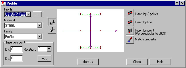
The Profile dialog has 3 main parts:
- On the left, you can specify basic information for a profile of a defined member:
- Profile - select a profile for a defined member (the most recently defined member profile is displayed). Click the (…) button to open the Profile listdialog, in which profiles from the available databases may be added to the list of available profiles.
- Material - select the type of a material assigned to a defined member
- Family - select a family (group) of members to which a defined member will be assigned
- Insertion point - define coordinates of the member shift (Dx and Dy offsets) and the rotation of a member profile about the member longitudinal axis (select a value from the list or enter one into the Rotation field). The offset denotes the shift of a profile center with respect to the insertion line
- In the middle is a graphical field that displays a selected profile of a defined member positioned in relation to the insertion line (under the graphical field, characteristic distances of the profile fibers from the profile axis are displayed). You can define offsets graphically, by using the cursor to shift a profile with respect to the axis or by specifying characteristic points of a profile. You can also define relative offsets (with respect to values related to the cross-section and characteristic points of a profile). Location of section characteristic points (their number depends on the section type and shape) may be determined by specifying certain values connected directly with the cross-section (these do not have to be absolute values). Characteristic points include:
- (0;0) center of gravity of a section
- Points presented in the drawing below whose coordinates are determined by the values Vy, Vpy, Vz, Vpz, Mid (they define a relative location of a point in the cross section)
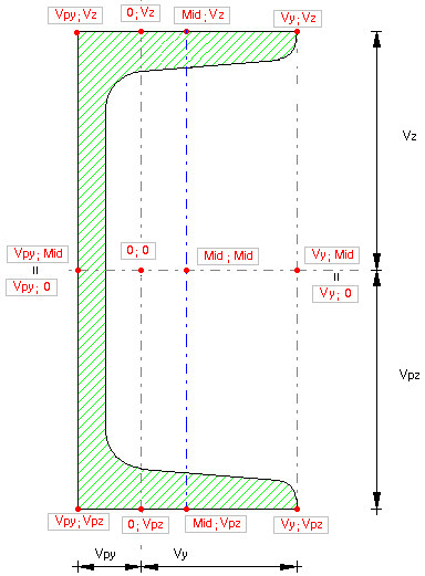
Profile characteristic points are marked in red in the dialog (in the drawing of a selected profile).
After you click on a characteristic point of a profile, the profile is translated and the edit fields Dx and Dy in the Insertion point field are populated automatically.
Under the schematic drawing, there is the More >> (or Less <<) button, which opens (closes) an additional field where you can specify:
- a surface finishing type for a profile (for example, hot-dip galvanized, electrogalvanized, anticorrosive paint, fireproof coat). A default type of surface finishing can be selected in the Project preferences dialog on the Materials tab; this dialog also allows adding a new surface finishing type or deleting a selected type from the list of available surface finishing types.
- profile properties (area, moments of inertia, and so on) - see the description of the Profile list dialog. After you right-click in this field, the context menu displays:
- Select All - selects the contents of the edit field
- Copy - copies the contents of the edit field to the Clipboard
- Paste - pastes the Clipboard contents to the edit field
The following icons are also available in this part of the dialog:
![]() - blocks the position of axes in the graphical field and lets you shift a profile
- blocks the position of axes in the graphical field and lets you shift a profile
![]() - blocks the position of a profile in the graphical field and lets you shift profile axes
- blocks the position of a profile in the graphical field and lets you shift profile axes
- Use the icons on the right to define the profile insertion:
 - 2 points
  - line
  - 1 point (a member will be defined as perpendicular to UCS)
  Match properties - used to adopt (inherit) parameters from a defined member profile.
When the Profile dialog displays, it displays the member profile parameters defined most recently.